doris@jshnbuzzer.com

SMD vs. Through-Hole Buzzer: Size, Mounting, and PCB Design
 Nov 09, 2026|
 View:8
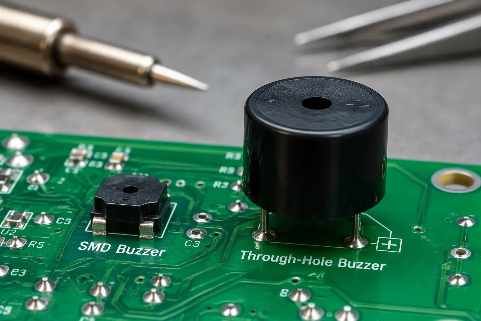
Buzzers ship in two package families: surface-mount (SMD) and through-hole. The package choice shapes board space, assembly flow, and layout long before a single component is placed. An SMD buzzer and a through-hole buzzer solve the same acoustic problem with different mechanical answers, and that is why the comparison keeps coming back at the layout stage.
Neither family is universally better. A compact wearable and a rugged industrial controller pull the decision in different directions, and the answer follows from the priorities of the design rather than from a specification table. Size, mounting method, and PCB design each carry real weight; application fit, cost at volume, and compliance requirements complete the picture. Both packages remain valid for the jobs they serve.
Key Takeaways
An SMD buzzer frees board area. The MLT-5020 measures 5.2 × 5.2 × 2 mm, while a 13.8 mm round through-hole housing covers roughly five times that footprint.
SMD buzzers run through the same reflow cycle as the rest of the board, with no separate insertion step.
Through-hole buzzers suit prototypes and rugged designs, because the pins anchor mechanically through the PCB.
Package and transduction technology are independent choices: piezo and electromagnetic versions exist in both formats.
Medical alarm designs must verify frequency response against IEC 60601-1-8, not just spot sound pressure level.
SMD vs. Through-Hole Buzzer: Size and Footprint
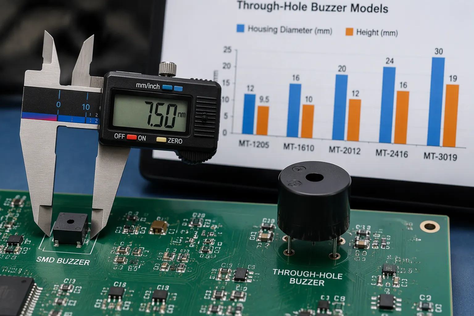
Package size drives the first real decision. An SMD buzzer is smaller than a through-hole buzzer, and it needs no drilled holes through the PCB. That single difference reshapes the available board area and, in dense designs, the layer count as well.
SMD Buzzer Size and Board Space
An SMD buzzer sits flat on the copper and consumes only the area of its pads. The HUAWHA line runs from 5.2 mm to 12 mm square, with heights from 2 mm to 4 mm, and output rises with footprint:
Model | Dimensions | SPL at 0.1 m | Frequency | Rated voltage |
|---|---|---|---|---|
MLT-5020 | 5.2 × 5.2 × 2 mm | 75 dB min | 4000 ± 200 Hz | 3.0 Vo-p |
MLT-5030 | 5.2 × 5.2 × 3 mm | 80 dB min | 4000 Hz | 3.0 Vo-p |
MLT-8530 | 8.5 × 8.5 × 3 mm | 85 dB min | 2700 ± 300 Hz | 3.6 Vo-p |
MLT-8540H | 8.5 × 8.5 × 4 mm | 85 dB min | 2700 Hz | 3.6 Vo-p |
MLT-1230 | 12 × 12 × 3 mm | 75 dB min | 4000 ± 500 Hz | 3 Vo-p |
The smallest parts sit at 5.2 × 5.2 mm, and the tallest at 4 mm. Against a 13.8 mm round housing, a 5.2 mm square pad pattern covers roughly one fifth of the board area. That difference is what pays for the wireless module, the power management, and the user interface in a wearable or a handheld instrument. Designers weighing SMD vs. Through-Hole Buzzer for a dense board usually find this the decisive number.
Through-Hole Buzzer Size and Height
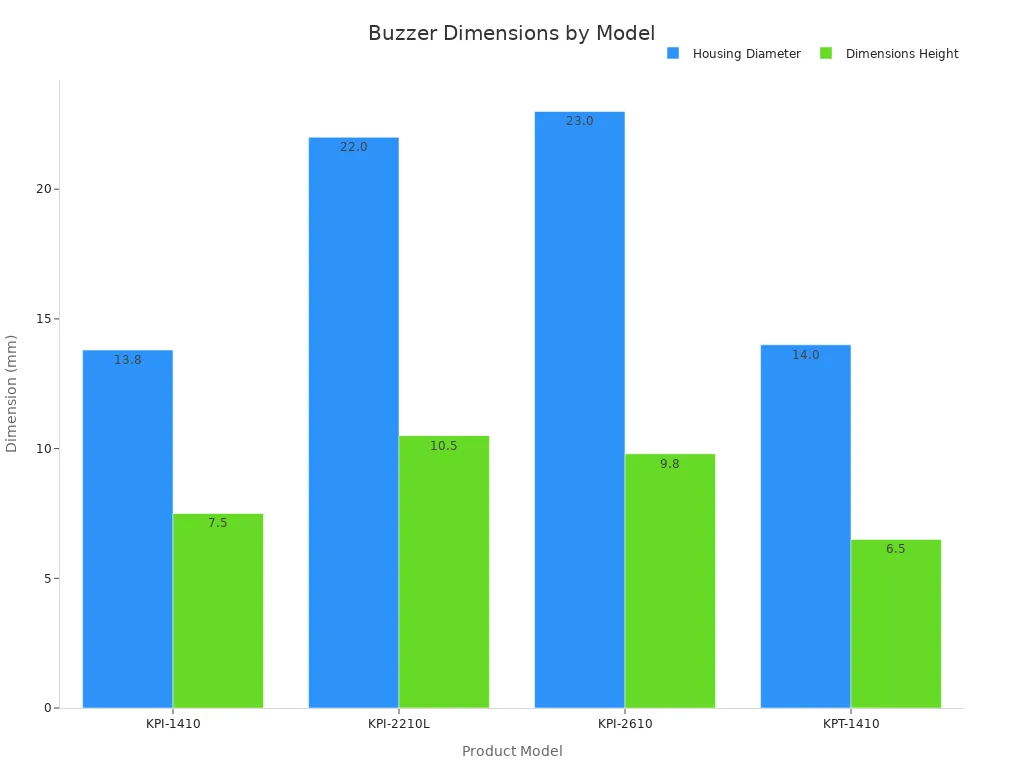
Through-hole buzzers occupy more board area and add height. The chart above plots four common housings: 13.8 mm diameter at 7.5 mm tall, 22.0 mm at 10.5 mm, 23.0 mm at 9.8 mm, and 14.0 mm at 6.5 mm. A through-hole part standing 7.5 mm to 10.5 mm tall forces the lid upward or pushes the PCB down, and that change propagates through every other mechanical decision in the enclosure.
Height matters most in low-profile enclosures. Keep the acoustic path from the sound port to the enclosure opening clear, and keep tall components out of the cone in front of the port. A related tradeoff is acoustic: smaller surface-mount types save board space, but their smaller sound chambers can reduce output, while through-hole housings carry larger chambers and support louder output in the same acoustic class.
Mounting and Assembly
Reflow for SMD Buzzers
An SMD buzzer joins the same reflow cycle as the rest of the board. Paste printing, pick-and-place, and oven reflow happen in one automated pass, and no separate operation is needed for the buzzer. This flow suits high-volume production, where every extra step adds cost and cycle time.
The buzzer body sees the full thermal profile. Confirm the part's rated reflow tolerance against the paste profile before release. Placement accuracy also matters, because the pads define where the acoustic port lands relative to the enclosure opening. Keep the port orientation consistent across the panel, and check the first article for port alignment before the run continues.
Wave and Hand Soldering for Through-Hole
Through-hole buzzers pass through wave soldering or hand soldering. Wave soldering handles the pins in a single pass on the bottom side, and hand soldering suits prototypes, rework, and low-volume builds. Both methods give a mechanically anchored joint through the plated hole.
Wave soldering demands attention to shadowing, since tall neighboring parts can block solder from reaching the pins. Pin spacing and orientation on the panel affect fill quality. Hand soldering gives the operator direct control, which helps on dense boards or unusual pin layouts. The tradeoff is labor time: each joint is made individually, so assembly cost scales with volume instead of amortizing across a panel.
PCB Design Considerations
Layout and Routing
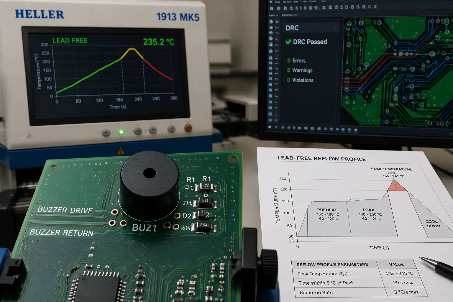
Buzzer layout follows the same discipline as any noise-sensitive circuit, with acoustic behavior added on top. Route the drive and return traces parallel and close together. That step minimizes loop area, lowers trace inductance, and keeps the buzzer lines from acting as radiating antennas.
The driver belongs close to the pads, because the load and the lead length both shape the waveform. A piezo buzzer presents a capacitive load driven by an oscillating signal, typically between 2 kHz and 4 kHz, and the drive stage has to deliver sharp edges to reach rated output. An electromagnetic buzzer presents an inductive load instead, so a flyback diode across the coil and a series resistor sized to the coil resistance belong in the circuit. Clamping the turn-off spike keeps the driving transistor inside its ratings.
Acoustic clearance deserves its own pass. No tall component should block the sound emission hole, and non-connected vias should not sit directly beneath the housing when the part needs a flush seat. Uneven mechanical stress on the pins can fracture internal electrodes over prolonged thermal cycling.
The rest of the layout follows standard mixed-signal practice: keep critical tracks short, separate digital and analog sections, use 45-degree corners rather than right angles, run power and ground tracks close together for effective bypassing, and tie every ground copper fill to ground. A design rule check should confirm the finished layout before release, and a first-article acoustic check should confirm the port position.
Thermal and Mechanical Stress
The reflow oven exposes the whole body to peak temperature, and an SMD buzzer and a through-hole buzzer respond differently. A through-hole part carries its mass on leads that flex with the board, while an SMD part carries it on solder joints that take the strain directly. Both need a profile that matches the paste and the part rating: preheat at 150–180 °C for 60–120 s, soak at 180–200 °C for 60–120 s, a peak of 235–245 °C, and 30 s or less within 5 °C of peak. SAC305 paste melts near 217 °C, and datasheets commonly cap the part at 260 °C for 10 seconds.
Ceramic elements can depolarize and micro-crack at high temperature. Confirm the moisture sensitivity level against J-STD-020, limit repeated reflow cycles, and avoid hand soldering near the buzzer to prevent thermal shock. IPC-A-610 sets the joint criteria to inspect against.
Vibration resistance is a debated topic. Through-hole pins anchor physically through the PCB substrate, which resists shock and structural vibration. A properly filleted SMD joint performs well in most vibration environments, and the surface-mount body carries less mass on shorter load paths. SMD joints can develop cracks under thermal cycling or vibration, while wire-leaded buzzers can develop fatigue breaks where leads exit the housing. Adhesive or mechanical fasteners reduce stress on the electrical connections in either case.
Mounting style | Where the load goes | Typical failure mode |
|---|---|---|
Through-hole | Pins carry it through the plated hole into the board | Fatigue break where the lead exits the housing |
SMD | Solder joints carry it into the pads | Crack initiation at the fillet heel |
SMD vs. Through-Hole Buzzer: Application Fit
Where SMD Fits
Compact, high-volume, automated designs map to the SMD buzzer. A typical surface-mount buzzer profile looks like this:
Consideration | Detail |
|---|---|
Size | 5.2 × 5.2 × 2 mm at the small end of the line |
Rated voltage | 3.0 Vo-p to 3.6 Vo-p on standard parts |
Sound pressure level | 75 dB to 85 dB at 0.1 m, rising with footprint |
Frequency output | 2700 Hz to 4000 Hz across the range |
Assembly | Reflow alongside the rest of the board, no insertion step |
Operating temperature | −20 °C to +70 °C on the standard line |
SMD buzzers run on automated SMT lines and suit compact consumer products, wearables, portable electronics, and densely packed boards. Confirm early whether the design needs an active indicator with an internal drive circuit or a passive transducer that requires an external square-wave signal, typically in the 2 kHz to 4 kHz range. That distinction matters more than package choice for the drive stage, and electromagnetic and piezo variants exist in both formats.
The size advantage has a limit. Smaller chambers produce less output, so an alert that has to cut through machinery noise may need a larger part, a different transduction principle, or a through-hole housing. Checking the SPL requirement against the ambient noise level at the operator position settles that question before the footprint gets locked in.
Where Through-Hole Fits
Rugged, low-volume, high-reliability designs map to the through-hole buzzer. Typical applications include industrial HMIs with panel-mounted alerts for machine start and stop, fault conditions, or cycle completion; medical equipment interfaces where EMI resilience matters; security systems; and logistics hardware such as scanning confirmation tones in rugged handheld terminals.
Pin-type terminations give a robust attachment, and many piezo buzzers tolerate temperature extremes, humidity, and mechanical shock. Models with IP-rated sealing are available, though sealing can slightly affect acoustic output. Prototypes, hand-assembled units, and field-serviceable instruments also favor this package, because a single joint can be desoldered and replaced without a rework station.
Cost and Volume
Unit Cost vs. Assembly Cost
The purchase price of a buzzer tells only part of the cost story, and the gap between an SMD buzzer and a through-hole buzzer rarely shows up in the quote. Assembly expense often outweighs the unit price difference between the two package families, and it is the line that changes most with volume.
Metric | Surface mount (SMT) | Through hole (THT) |
|---|---|---|
Assembly speed | Line rate, with AOI or X-ray inspection | Slower, with drilling plus selective or wave soldering |
Cost efficiency | Low at scale, plus the smaller board area | Higher per joint, favorable below a few hundred units |
Tooling | Stencil and paste setup | Drill program and fixture only |
Rework | Hot-air or infrared station | Single joint with a soldering iron |
Placement runs at line rate on automated equipment, and inspection follows through AOI or X-ray. Through-hole assembly moves more slowly, because drilling, selective soldering, and wave soldering each add a step to the flow. On a board with one buzzer the difference looks small; on a board with twenty through-hole parts it defines the schedule.
Prototype vs. Production Volume
Prototype builds favor simplicity over scale. Hand soldering a through-hole buzzer takes minutes and needs no stencil, no paste, and no reflow profile. A designer can swap the part during bench testing without scrapping a panel, which matters when the acoustic target is still moving.
Production volume reverses the logic. Automated SMT lines spread their setup cost across thousands of units, and the per-board assembly cost falls accordingly. Predictable output and faster cycle times favor the surface-mount route once volume is high enough to absorb the setup. The SMD vs. Through-Hole Buzzer cost comparison therefore depends on order size as much as on part price: a low-volume run may never recover the tooling investment behind an SMT line, and a high-volume run rarely justifies the labor of manual insertion.
Regulatory and Compliance
Solder and Material Compliance
RoHS restricts hazardous substances in the finished part, and the restriction reaches the solder joint as well as the buzzer body. Lead-free reflow profiles follow from that requirement, which is why datasheets publish peak temperature limits. In the EU, RoHS compliance is declared through the CE marking process rather than handled as a separate approval, and the declaration covers the finished product, not just the buzzer.
Both package families can meet these requirements. The compliance work sits in the material declaration and the process documentation, not in the mounting style. Request the RoHS declaration and the CE documentation from the supplier and file them with the build records. A buzzer that survives reflow but lacks the paperwork still blocks a product release.
The scope of the directive, the substances it covers, and the records a buyer should expect are set out in official RoHS compliance guidance [1].
Acoustic and Safety Standards
Alarm and instrumentation designs often carry acoustic standards on top of material compliance. IEC 60601-1-8 governs medical device alarm systems and specifies basic safety and performance requirements for the alarm signals themselves, which is a different scope from the electrical safety rules that apply to the rest of the instrument.
In the U.S., Canada, and the EU, compliance is mandatory for medical devices placed on the market. The FDA recognizes the standard for alarm systems, and the current recognized edition is ANSI/AAMI/IEC 60601-1-8, Edition 2.2. A buzzer selected for a medical alarm therefore needs its frequency response checked against these limits, not just its sound pressure level at one tone. The list of recognized editions is published in the FDA consensus standards database [2].
The standard sets concrete acoustic criteria:
The alarm frequency must fall between 150 Hz and 1000 Hz and must be one of the four harmonics with the highest sound level.
At least four frequency peaks must appear between 150 Hz and 4000 Hz.
The four loudest peaks between 150 Hz and 4000 Hz must sit within 15 dB of each other.
The standard defines the alarm pulse frequency range, pulse shape, rise and fall time, and burst pattern.
It prescribes sound levels in decibels by alarm priority.
It sets a maximum amplitude difference between alarm pulses.
Peer-reviewed work on alarm design in clinical settings is indexed in the biomedical literature [3], and it is a better starting point than a vendor summary when an alarm strategy has to be defended in a design review. Read the standard itself before the first acoustic prototype, because the harmonic requirements shape the drive waveform, not just the buzzer choice.
SMD suits compact, automated, high-volume designs, and the SMD buzzer reaches the smallest footprints in the line. Through-hole delivers mechanical robustness, easy prototyping, and hand assembly, which is why the through-hole buzzer still anchors industrial panels. The SMD vs. Through-Hole Buzzer decision follows from the application's priorities rather than from a single specification.
A short guide maps the common scenarios:
Priority | Package | Why |
|---|---|---|
Wearable or handheld, tight enclosure | SMD | 5.2 mm square pad pattern, 2 mm height |
Industrial panel, shock and vibration | Through-hole | Pins carry the load through the plated hole |
Prototype under a few hundred units | Through-hole | No stencil, no paste, easy to swap |
High-volume consumer product | SMD | Reflows in the same pass as the rest of the board |
Medical alarm in 60601-1-8 scope | Either | Choose by footprint and drive stage, then verify frequency response |
Field-serviceable instrument | Through-hole | A single joint can be replaced without a rework station |
Match the package to the design's priorities, and the decision becomes straightforward.
SMD Buzzers from HUAWHA

MLT-5020
5.2 × 5.2 × 2 mm
75 dB min at 0.1 m

MLT-5030
5.2 × 5.2 × 3 mm
80 dB min at 0.1 m

MLT-8540H
8.5 × 8.5 × 4 mm
85 dB min at 0.1 m
FAQ
How small can an SMD buzzer get?
The smallest parts on the HUAWHA line measure 5.2 × 5.2 × 2 mm, and heights run from 2 mm to 4 mm across the range. Footprint grows with output: a 5.2 mm part reaches 75 dB to 80 dB at 0.1 m, while an 8.5 mm part reaches 85 dB. These parts suit dense boards where every square millimeter counts, as long as the acoustic target stays within reach of the chamber volume.
Can an SMD buzzer survive the reflow oven?
Yes, within its rated profile. An SMD buzzer rides the same lead-free reflow cycle as the rest of the board: peaks at 235–245 °C, and datasheets commonly cap the part at 260 °C for 10 seconds. Confirm the moisture sensitivity level, keep the time within 5 °C of peak under 30 s, and limit repeated reflow cycles to protect the ceramic element or coil assembly.
How much clearance does a buzzer need above the board?
Keep the path from the sound port to the enclosure opening clear. No tall component should sit in front of the port, and the port should not be pressed against a flat surface that seals it. Where the design uses a front cavity, its volume and the opening area set the low-frequency response, so confirm the target against the supplier's acoustic curve rather than a fixed number.
Which package handles vibration better?
On a through-hole buzzer the pins anchor physically through the PCB substrate, which resists intense shock. A properly filleted SMD joint also performs well in most vibration environments, and the surface-mount body carries less mass on shorter load paths. The failure modes differ: leads fatigue where they exit the housing, and SMD joints crack at the fillet heel. Adhesive or mechanical fasteners reduce stress on either connection.
What compliance documents should I request?
Ask the supplier for the RoHS declaration and the CE documentation, and file both with the build records. Medical alarm designs also need the frequency response verified against IEC 60601-1-8 limits, not just the sound pressure level at one tone, so request the acoustic curve along with the specification sheet.
Sources
RoHS compliance guidance, on the scope of the directive and the records a buyer should expect.
FDA consensus standards database, for the recognized edition of ANSI/AAMI/IEC 60601-1-8.
Biomedical literature index, for peer-reviewed work on medical alarm design.
Model dimensions and acoustic figures for the MLT series are taken from HUAWHA product datasheets. Through-hole housing dimensions in the chart correspond to the models plotted.