doris@jshnbuzzer.com

How to Choose the Right Buzzer for Your Electronic Device
 Nov 03, 2026|
 View:3
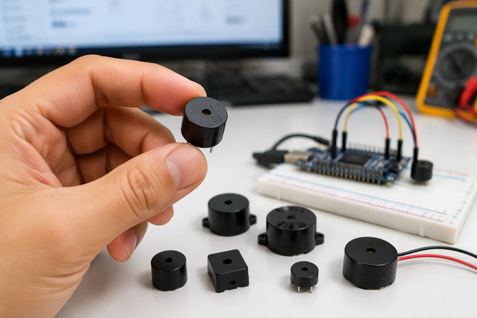
The right buzzer for an electronic device is the one whose specifications perfectly match the application. Five core specifications drive the decision: buzzer type, frequency, sound pressure level (SPL), power, and size or mounting. Each one narrows the field further. A mismatch in any single specification can leave a device that is too quiet, too large, or incompatible with its drive circuit.
This guide follows a logical engineering sequence. It starts with buzzer type and moves through frequency, sound pressure level, power, and mounting, ending with practical bench testing. Follow this sequence to choose the right buzzer with absolute confidence.
Key Takeaways
Choose the right buzzer type first: piezoelectric or magnetic, and active or passive.
Pick a frequency near the buzzer's resonant point for the loudest sound output.
Check sound pressure level ratings at the exact same distance and drive conditions.
Match voltage, current, and physical size to your circuit and PCB board space.
Always test the buzzer inside the real enclosure before committing to mass production.
How to Choose the Right Buzzer Type
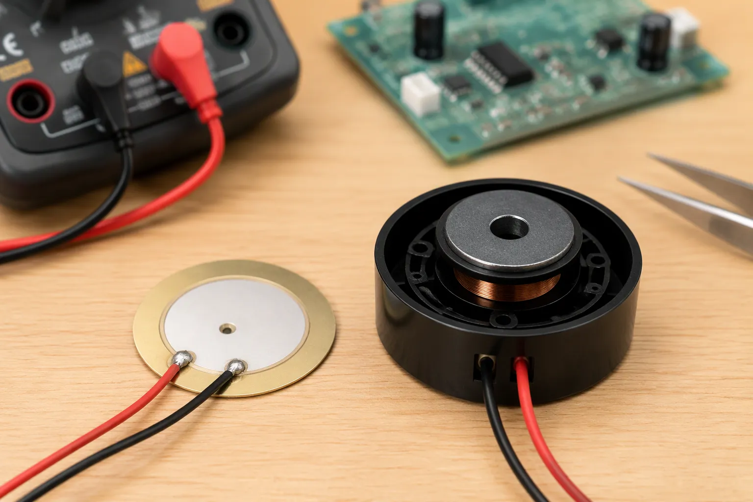
The first decision is the buzzer type. Two classifications matter: the sound-generating principle (piezoelectric or magnetic) and the drive requirement (active or passive). Each classification shapes the circuit, the firmware, and the physical fit. Working through both narrows the field before frequency and sound pressure level enter the picture.
Piezoelectric vs. Magnetic Buzzers
The two families differ fundamentally in construction. A magnetic buzzer drives current through a tightly wound voice coil, and the resulting magnetic field moves a ferromagnetic diaphragm. A piezoelectric buzzer applies voltage across a ceramic element bonded to a metal plate, and the element deforms to produce sound. This architecture makes piezo types thin and light, while magnetic types tend to be larger and heavier due to the inclusion of a permanent magnet and magnetic circuit. From a circuit design perspective, a piezo buzzer is modeled as a capacitor, while a magnetic buzzer is modeled as a coil in series with a resistor — a difference that directly affects driver design.
The electrical profiles differ as well. Piezo buzzers typically draw under 10 mA and resonate between 2 kHz and 6 kHz. Magnetic buzzers commonly draw 20 mA to over 60 mA and resonate from 1 kHz to 3 kHz.
Parameter | Piezo Buzzers | Magnetic Buzzers |
|---|---|---|
Current draw | typically <10 mA | commonly 20 mA to over 60 mA |
Resonant frequency | typically 2 kHz to 6 kHz | 1 kHz to 3 kHz |
Piezo types fit low-power and space-constrained designs, such as handheld instruments and compact SMD assemblies. Magnetic types suit applications that need a warmer tone or a lower resonant frequency, including alarms and appliance alerts. Both meet CE and RoHS requirements when sourced from a compliant supplier like JSHN Buzzer.
Active vs. Passive and Drive Circuits
An active, or indicator, buzzer contains an internal oscillator. It produces sound when a DC voltage is applied. A passive, or transducer, buzzer has no internal oscillator and needs an external waveform, typically a square wave in the 2 kHz to 5 kHz range.
Buzzer Type | Drive Signal Requirement |
|---|---|
Active buzzer | DC voltage; internal oscillator generates the tone |
Passive buzzer | External square wave, typically 2 kHz to 5 kHz |
The choice heavily affects firmware. An active buzzer needs only simple on/off control, which preserves microcontroller timers and PWM resources for motors, communication, and lighting. A passive buzzer requires timer or PWM waveform generation but allows multiple pitches, sirens, and melodies.
Choose an active buzzer for a simple fixed beep. Choose a passive buzzer when the sound frequency itself must carry information or when the product needs customized tones.
Passive transducers connect directly to most microcontroller pins, and toggling both pins in opposite polarity can increase output. To choose the right buzzer, match the drive classification to the firmware budget and the tone requirements. A design with a fixed alert and a tight firmware schedule favors the active type. A design that encodes different conditions in different tones favors the passive type.
Pick the Right Frequency and Tone
Resonant Frequency and Output
Every buzzer has a resonant frequency, the point where its diaphragm vibrates most efficiently. Driving the part near this point converts more electrical energy into sound. Typical resonant frequencies are 2 kHz to 6 kHz for piezo buzzers and 1 kHz to 3 kHz for magnetic buzzers.
Buzzer Type | Typical Resonant Frequency |
|---|---|
Piezo Buzzers | 2 kHz to 6 kHz |
Magnetic Buzzers | 1 kHz to 3 kHz |
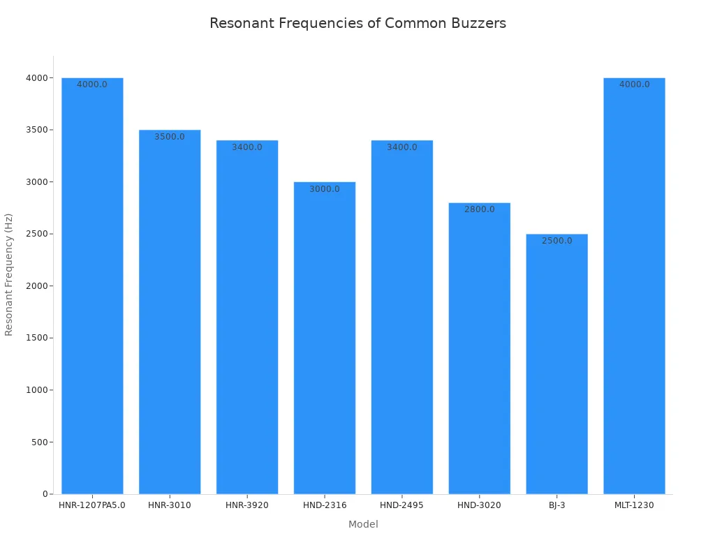
A passive buzzer driven away from resonance loses output for the same drive voltage. At JSHN Buzzer, we engineer models with rated frequencies optimized for specific acoustic targets. The chart below shows resonant frequencies for eight buzzer models across a common span.
Audible Range and Tone Character
According to psychoacoustic principles and equal-loudness contours (such as ISO 226), the human ear is most sensitive between 2,000 and 5,000 Hz. Many buzzers are designed to operate in this band for easy detectability. A 2.5 kHz tone reads as sharp and attention-grabbing, which suits emergency alerts. A 1.5 kHz tone sounds deeper and less piercing, which fits routine notifications. Tones around 3 kHz to 4 kHz cut through background noise more effectively in industrial settings.
Tone character also depends on the application. Short pulses under 500 ms, built on lower fundamental frequencies with added harmonics, are easier to distinguish in noisy environments. Lower tones near 520 Hz are often proven to wake sleepers more effectively than traditional high-pitched alarms. Frequency choice interacts with size as well; buzzer size affects both volume and pitch. A compact design therefore trades some low-frequency reach for space.
Set Sound Pressure Level for Audibility
Reading SPL Ratings Correctly
A sound pressure level (SPL) rating means little without its measurement conditions. Manufacturers typically measure SPL at a stated distance, often 10 cm or 30 cm, under a specific drive voltage and frequency. Understanding datasheet parameters is therefore a starting point, not a guarantee.
Condition | Distance | Drive/Operating Conditions |
|---|---|---|
Datasheet Standard | 10 cm or 30 cm | Rated Voltage at Resonant Frequency |
Free-field Estimation | 1 meter | Calculated via Inverse Square Law |
Installed Environment | User Ear Distance | Affected by Enclosure and Ambient Noise |
Distance, Enclosures, and Ambient Noise
Distance erodes loudness predictably in open air. According to the inverse square law of sound, sound pressure drops about 6 dB for every doubling of distance: 100 dB at 1 m becomes roughly 94 dB at 2 m and 88 dB at 4 m. An 85 dB rating at 10 cm falls to approximately 79 dB at 20 cm.
Doubling distance does not always reduce the alarm by exactly 6 dB. That figure is an ideal free-field point-source estimate. Reflections, obstructions, directionality, and other sound sources will change the actual installed result.
Enclosure design and acoustic coupling compound the effect. JSHN Buzzer recommends placing the buzzer at the board edge so sound escapes through vents unobstructed, as slight position shifts can drastically change acoustics. Ambient noise sets the real target: 75 dB at 10 cm is suitable for close-proximity devices such as smartwatches, while industrial or automotive settings demand 90 dB or higher. Environmental conditions also matter. Always check moisture exposure and operating temperature ranges, and test under actual operating conditions.
Match Power, Size, and Mounting
Voltage, Current, and Drive Compatibility
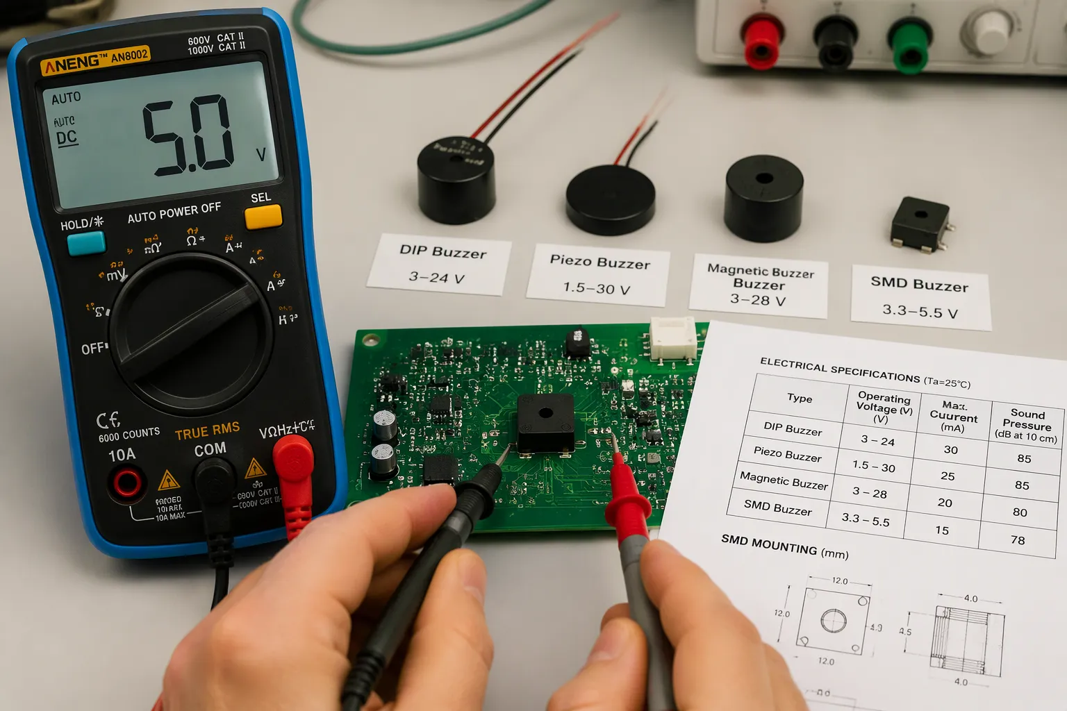
The electrical interface decides whether a buzzer works reliably in a given circuit. Drive voltage comes first. Self-drive indicators typically accept 3 to 28 Vdc, while non-self-drive transducers take a 1 to 60 Vp-p signal. Common SMD parts sit at 3 V, 5 V, or 12 V.
Drive Type | Voltage Range | Notes |
|---|---|---|
Self-drive (indicator) | 3–28 Vdc | Includes SMD indicators at 12 V, 3 V, and 5 V |
Non-self-drive (transducer) | 1–60 Vp-p | Includes SMD transducers at 3.6 Vo-p and 5 Vp-p |
Current draw follows the same split. Magnetic buzzers generally draw 20 to over 60 mA, while piezo types operate at very low consumption. A battery-powered design therefore leans toward piezo, while a mains-powered alarm can easily absorb the magnetic draw.
Duty cycle deserves attention in continuous-tone designs. Limiting duty cycles to under 50 percent for continuous tones helps avoid premature wear and extends component lifespan. When the supply voltage varies, do not pick a part on sound level alone. Check that the minimum supply still starts the oscillator and that the maximum stays within the rated window.
SMD and Mounting Options for Compact Designs
Buzzers mount three common ways: through-hole DIP, wire leads, and surface mount. DIP and wire types suit hand assembly and panel wiring. SMD types suit automated reflow on dense boards.
SMD buzzers fit compact designs best. The typical SMT buzzer is highly compact, easily attached to a PCB via automated reflow. In a model number such as SMT1230, "SMT" means surface mounting, "12" gives the diameter, and "30" gives the height. Compact SMD parts can be as small as 5 mm by 5 mm by 2 mm, offering 70 dB to 80 dB output at 10 cm with frequencies often between 2 kHz and 4 kHz.
Size trades against output. Smaller size can limit sound output, so tiny parts may not suit high-volume alert applications. SMD piezo buzzers may not fit applications requiring extremely high sound output and are better suited to simple tones than complex sounds. Higher SPL typically comes from larger buzzers or higher drive voltages. To choose the right buzzer for a compact product, accept a lower output target or allocate more board area.
Choose the Right Buzzer Volume and Testing
Practical Tips to Maximize Output
Volume begins with the drive signal. A passive buzzer produces its loudest sound at resonance, and the datasheet lists that frequency. Drive the part at that point rather than at an arbitrary tone. Operating at or near the resonant frequency maximizes efficiency and sound pressure level. A resonant drive circuit can raise output further. It pairs the piezo element's capacitance with an inductor, allowing the voltage across the buzzer to reach many times the supply voltage at high electrical efficiency.
The enclosure decides how much of that output reaches the ear. Sealing the back of the transducer inside an airtight enclosure stops rear radiation from canceling the front wave, which can yield a gain of up to 6 dB. A loose mount inside a large sealed box does the opposite and destroys sound pressure level. Port placement matters equally:
Keep tall components such as electrolytic capacitors, heat sinks, and connectors clear of top-port sound emission holes.
Align the casing hole directly over the buzzer cavity, and leave at least 1.5–2.0 mm between the buzzer top and the enclosure wall so sound waves resonate cleanly.
Bench Testing Before Production
Datasheet figures describe a reference setup, not the finished product. Test the prototype inside the actual enclosure and under real ambient conditions before committing to production. Verify the real enclosure before freezing the bill of materials. Measure at the distance the user will hear the alert, and repeat the test at the quietest and noisiest points of the operating environment.
A final review confirms each decision. Check the type against the drive circuit, the frequency against the tone requirement, the sound pressure level against ambient noise, and the power, size, and mounting against the board. Readers who follow this sequence can choose the right buzzer with confidence, because every specification has been matched to the application rather than judged alone.
The decision checklist covers type, frequency, sound pressure level, power, size and mounting, and cost. Each specification must match the application. No single specification works in isolation. A loud buzzer with the wrong drive voltage still fails. A compact SMD part with insufficient output still fails.
Datasheet figures are starting points. They describe a reference setup, not the finished device. Prototype testing inside the actual enclosure under real ambient conditions is the decisive step. Measure at the distance the user will hear the alert.
To choose the right buzzer, match every specification to the device requirements at acceptable cost. That balance defines the correct part.
FAQ
Should I choose an active or passive buzzer?
An active buzzer needs only a DC voltage and suits fixed alerts. A passive buzzer needs an external square wave, typically 2 kHz to 5 kHz, and suits designs that vary pitch or tone. Match the choice to the firmware budget and the tone requirement.
At what distance should I compare SPL ratings?
Compare ratings only at the same distance and drive conditions. Datasheets commonly measure at 10 cm or 30 cm. An 85 dB rating at 10 cm falls to roughly 79 dB at 20 cm, so a rating without its distance is not comparable.
Which frequency should I pick for an alarm?
The ear is most sensitive between 2,000 and 5,000 Hz. Tones near 2.5 kHz read as sharp and attention-grabbing for emergency alerts. Lower tones near 1.5 kHz suit routine notifications. Match the tone character to the application.
Are SMD buzzers loud enough for compact devices?
SMD buzzers fit dense boards, with compact parts measuring as small as 5 mm by 5 mm by 2 mm. Output typically reaches 70 dB to 80 dB at 10 cm. Smaller size limits sound output, so confirm the target against the application.
Do I need to test the buzzer in the enclosure?
Yes. Datasheet figures describe a reference setup, not the finished device. Enclosure design, port placement, and ambient noise change the installed result. Test the prototype inside the actual enclosure under real conditions before committing to production.
Need Help Selecting the Perfect Buzzer?
Choosing the right acoustic component can be complex. Our engineering team at JSHN Buzzer is ready to help you match the exact specifications to your application and provide custom acoustic solutions.
Contact Our Engineers