

 doris@jshnbuzzer.com
Electromagnetic Buzzer Buying Guide for Your Next Project
 Sep 07, 2026|
 View:394
Designing the acoustic feedback for your next hardware project shouldn't be a guessing game. Whether you're engineering a battery-powered IoT sensor, a life-saving medical device, or an automotive dashboard, selecting the right electromagnetic buzzer is critical for both user experience and power efficiency. In this comprehensive engineer's guide, we cut through the datasheet jargon to help you navigate the trade-offs between electromagnetic and piezo technologies, decode critical SPL ratings, and design bulletproof driver circuits. By the end, you will be equipped to select the ideal acoustic component for your specific application.
Key Takeaways
Electromagnetic buzzers produce lower tones and need more current than piezo buzzers.
Piezo buzzers draw less power and work at higher voltages, making them good for battery devices.
Check the rated voltage and current to match your power supply and avoid damage.
Active buzzers have a built-in oscillator; passive buzzers need an external signal.
Use an NPN transistor and a flyback diode to drive a passive electromagnetic buzzer safely.
Choose a buzzer with a higher SPL rating for noisy environments.
Select a sealed buzzer for damp or outdoor conditions to prevent damage.
Define your voltage and sound needs first, then pick a buzzer that fits.
Electromagnetic Buzzer vs. Piezoelectric Buzzers
What Is an Electromagnetic Buzzer?
Core Components and Working Principle
An electromagnetic buzzer converts electrical energy into sound through magnetism. The core components include a coil, a permanent magnet, and a thin metal diaphragm. When current flows through the coil, it creates a magnetic field that attracts or repels the diaphragm. This movement produces sound waves. The housing protects internal parts and amplifies the acoustic output.
The piezoelectric effect operates differently. A piezo buzzer uses a ceramic crystal that changes shape when voltage is applied. This deformation creates vibrations that generate sound. The piezo element itself serves as both the driver and the diaphragm. No coil or magnet exists in this design.
Sound Generation and Frequency Response
The electromagnetic buzzer excels at lower frequencies. Its mechanical construction allows deeper tones that travel well through enclosures. The diaphragm movement creates a softer, mellower sound compared to piezo alternatives. This characteristic suits applications requiring pleasant alerts rather than harsh tones.
Piezo buzzers produce higher-pitched sounds. Their resonant frequency sits much higher in the audible spectrum. The output peaks sharply at resonance, creating a piercing tone. This narrow operating band limits flexibility for varied audio signals. However, piezo units achieve higher SPL values at their resonant point.
Key Differences Between Buzzer Types
Power Consumption and Size Trade-offs
Piezo buzzers draw extremely low current, typically under 30mA across a wide voltage range from 3V to 250V.
Electromagnetic buzzers consume more power, ranging from 20mA to over 100mA, but operate at lower voltages between 1.5V and 30V.
The piezo's minimal current draw extends battery life significantly in portable devices.
Magnetic units require thicker profiles due to the coil and magnet assembly, often exceeding 5mm in height.
The size difference matters for compact designs. Piezo buzzers can be thinner than 3mm, making them ideal for wearables and slim gadgets. The electromagnetic buzzer's heavier construction provides better shock resistance but occupies more board space.
Sound Output and Frequency Characteristics
Parameter | Piezo Buzzers | Electromagnetic Buzzers |
|---|---|---|
Frequency Response | Broad (Wideband) | Narrow (Peaks at Resonance) |
SPL Output | Very High (at resonant peak) | Moderate to High (Consistent across band) |
Resonant Frequency | High | Lower |
Operating Voltage | Higher | Lower |
Current Requirement | Ultra-low (µA to low mA) | Moderate (20mA - 100mA) |
Piezo buzzers deliver exceptional loudness at resonance, often exceeding 100dB. Their efficiency per decibel remains high across the operating range. Electromagnetic buzzers typically produce 70-85dB at 10cm distance. The trade-off involves frequency response width. Magnetic units offer a wider usable band below resonance, while piezo performance drops sharply off-resonance.
How to Choose the Right Buzzer Type
Matching Buzzer Type to Application Needs
Consider the end product's requirements carefully. Electromagnetic buzzers suit low-voltage alarms, doorbells, timers, and automotive signals. Their better low-frequency response supports voice output and musical notes. These applications need strong audible warnings with softer tonal quality.
Piezo buzzers excel in battery-powered devices where current conservation matters. Their high-frequency output penetrates ambient noise effectively. HUAWHA offers both types, including the 12VDC 85dB Piezo Buzzer for comparison against electromagnetic models. The piezo's compact size and low power draw make it suitable for portable electronics and instrumentation.
Considering Power Source and Driver Circuit
The available power supply determines the practical choice. Electromagnetic buzzers operate efficiently at 1.5V to 12V, matching common battery configurations. Their current-driven nature requires a transistor switch and flyback diode for proper integration. The coil's inductive load demands protection against voltage spikes.
Piezo buzzers need higher drive voltages but minimal current. A simple resistor network often suffices for the driver circuit. The capacitive load presents no inductive kickback concerns. For microcontroller projects, the piezo's voltage-driven characteristic simplifies interface design. However, the electromagnetic buzzer's lower voltage requirement may eliminate the need for boost converters in 3V systems.
Both types of buzzers serve distinct purposes. The selection ultimately depends on voltage availability, current budget, and desired acoustic performance. HUAWHA's product range includes SMD, pin, and lead buzzer configurations to match diverse mounting requirements.
Key Electrical Specifications for Buzzers

A datasheet contains the information you need to select the correct component. Understanding each parameter prevents costly design errors. This section explains the critical electrical specifications found on every buzzer datasheet.
Voltage and Current Requirements
Understanding Rated vs. Operating Voltage
Every buzzer carries a rated voltage, which represents the optimal supply level for peak performance. The operating voltage range, however, defines the boundaries within which the buzzer functions safely. Operating outside this range can damage the buzzer or result in low sound output.
Drive Type | Operating Voltage Range |
|---|---|
Self-drive (indicator) | 3–28 Vdc |
Non-self-drive (transducer) | 1–60 Vp-p |
Magnetic buzzers operate at lower voltages compared to piezo alternatives while drawing higher currents. This lower-voltage operation distinguishes them from piezo counterparts in typical applications. A 5VDC rated buzzer, for instance, might accept 3–8Vdc input. Supplying 12Vdc to that same component would overheat the coil and degrade the acoustic output permanently.
Calculating Current Draw for Your Power Supply
Current consumption determines whether your power supply can handle the load. The HUAWHA 5VDC 85dB Mini Pin Buzzer draws a modest current during operation. To calculate total current draw, multiply the buzzer's rated current by the number of buzzers in your design. Add this figure to the current requirements of every other component. Compare the sum against your power supply's maximum output rating. Reserve at least 20% headroom to accommodate transient spikes during startup.
Sound Output and Frequency
Decoding Sound Pressure Level (SPL) Ratings
Sound Pressure Level (SPL) quantifies acoustic output in decibels (dB). Manufacturers measure SPL at a fixed distance, typically 10 cm or 30 cm from the buzzer source. Typical SPL values range from 70 dB to over 100 dB for PCB audible alerts.
Physical Change | dB Increase | |
|---|---|---|
Doubling sound pressure | +6 dB | Not perceived as twice as loud |
Smallest audible change | +3 dB | Just noticeable difference |
Perceived doubling of loudness | +10 dB | Sound subjectively appears twice as loud |
A 3 dB change is clearly audible to the average listener. A 10 dB change feels roughly "twice as loud" to human perception. The HUAWHA 24VDC 110dB Mini Alarm exemplifies a very loud buzzer suitable for industrial environments. Sound intensity decreases by 6 dB for every doubling of distance. An 85 dB rating at 10 cm becomes approximately 79 dB at 20 cm. For close-proximity devices like smartwatches, 75 dB at 10 cm suffices. Industrial or automotive settings demand 90 dB or higher to overcome background noise. SPL above 100 dB at close range can be startling or harmful, so testing in the intended environment is recommended.
The Importance of Resonant Frequency
Resonant frequency defines the point where the buzzer vibrates most efficiently. For magnetic buzzers, this range typically spans 1 kHz to 3 kHz. Driving the buzzer with an input signal at or near its resonant frequency produces the maximum SPL with minimal input power. The buzzer can still operate across its specified frequency range, but output drops as the input deviates from resonance. A passive buzzer driven at its resonant frequency delivers the loudest output for the least electrical energy. Designers seeking maximum efficiency should match the driving frequency to the datasheet's resonant frequency specification.
Active vs. Passive Buzzers
Built-in Oscillator vs. External Signal
The fundamental difference between active and passive buzzers lies in the internal oscillation source. An active buzzer contains a built-in oscillator that converts DC input into the required audio-frequency signal internally. Applying only the appropriate working voltage across the electromagnetic coil produces sound. A passive buzzer lacks this internal oscillator, requiring an external waveform to drive it. Changing the waveform frequency directly changes the resulting noise.
Feature | Active Buzzer | Passive Buzzer |
|---|---|---|
Internal oscillator | Built-in | None |
Power source | DC voltage (1.5V–24V) | AC signal required |
Sound frequency | Fixed ~2kHz±300Hz | Variable based on input frequency |
Coil resistance | Lower (~16Ω) | Higher (typically >16Ω) |
Current draw | ≤25mA | ~36mA (may need 100Ω series resistor) |
Behavior on DC connection | Continuous loud tone | Pop/click sound (like a relay) |
Implications for Microcontroller Projects
The active buzzer simplifies circuit design considerably. Because the oscillator is integrated, the external circuit does not need a separate waveform generator or continuous PWM output. A compatible DC voltage alone produces a continuous tone. The host controller manages the buzzer with a simple on/off command, preserving microcontroller timer resources for other functions. This approach suits projects requiring a fixed alert tone without firmware complexity.
The passive buzzer demands more from the controller. It requires an external square wave, PWM, or alternating drive signal along with a driver stage. This added complexity brings flexibility. The passive buzzer can vary pitch and tone, enabling musical notes and complex alert patterns. For projects needing multiple sound profiles, the passive buzzer justifies the additional circuit components. The trade-off between simplicity and versatility guides the selection between these two buzzer types.
Selecting the Right Buzzer for Your Project
Physical Size and Mounting Options
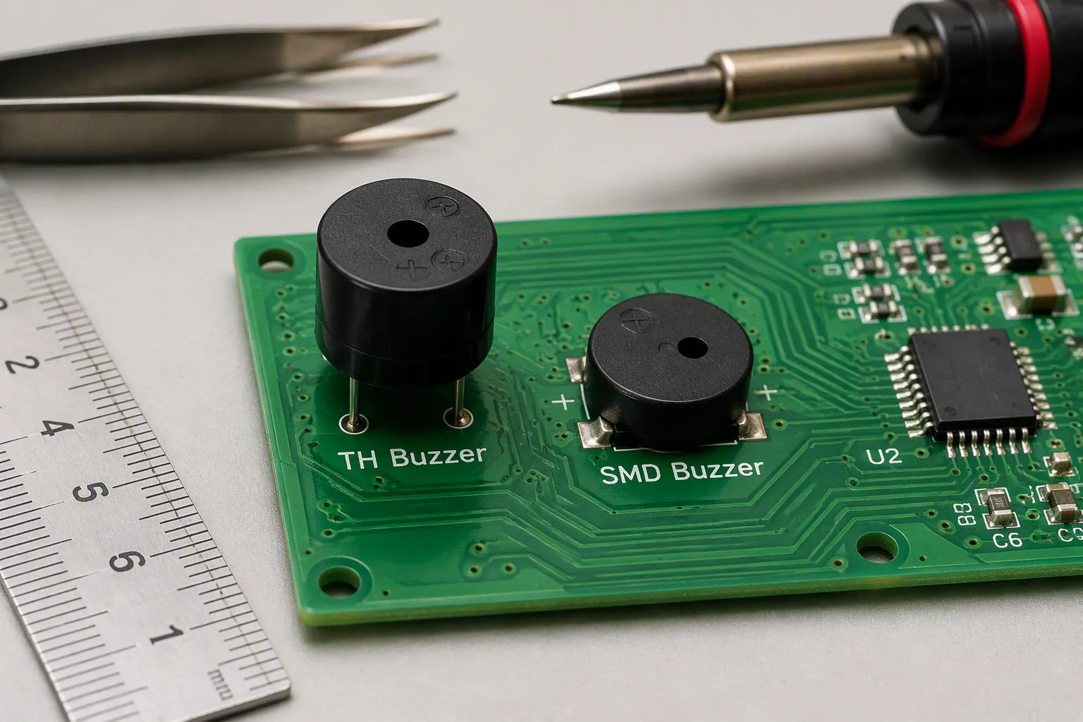
Through-Hole vs. SMD for Your PCB
The mounting style determines your assembly process and board layout. Through-hole buzzers feature pins that insert into drilled holes. This method provides strong mechanical anchoring. The solder joint remains visible for inspection. Through-hole components suit prototyping and hand-soldering workflows. They withstand vibration better than surface-mount parts.
Surface-mount (SMD) buzzers attach directly to pads on the PCB surface. This approach eliminates drilling requirements. SMD components enable smaller board footprints. Automated pick-and-place machines handle these parts efficiently. High-volume production benefits from reduced assembly time. HUAWHA offers both SMD and pin buzzer configurations to match diverse manufacturing needs.
The choice affects your design process. Through-hole parts require larger board area. The holes consume space on every layer. SMD parts free up routing channels beneath the component. However, SMD buzzers demand precise placement during assembly. The land pattern must follow IPC-7351 guidelines. This standard prevents tombstoning or bridging during reflow soldering.
Evaluating Size Constraints in Your Design
Board space often dictates the buzzer selection. Measure the available area before choosing a component. Consider the height clearance above the PCB. Enclosure designs may limit the buzzer's profile. The electromagnetic buzzer typically requires more vertical space than a piezo buzzer. The coil and magnet assembly adds thickness.
Position the buzzer on the board edge. This placement allows unobstructed sound propagation. The acoustic output escapes through enclosure vents more easily. Place the buzzer away from sensitive analog circuitry. The magnetic field can interfere with nearby components. Use wide traces for power routing to minimize voltage drops. Implement ground planes to reduce noise coupling into signal lines.
Test placements before final soldering. Slight shifts can drastically change acoustics. The buzzer's position relative to enclosure openings matters significantly. A firm solder joint prevents intermittent failures. Double-check polarity to avoid component damage. Use a fine-tired iron with just enough solder to prevent shorts or weak connections.
Environmental and Durability Factors
Operating Temperature Range
Temperature extremes affect buzzer performance and lifespan. Standard electromagnetic models operate reliably between -20°C and +70°C. This range covers most indoor consumer applications. Industrial environments with higher temperatures may require specialized versions. According to manufacturer specifications for active electromagnetic buzzers, industrial-grade units operate from -40°C to 85°C. This extended range suits factory automation and outdoor equipment.
The operating temperature affects the coil's resistance. Higher temperatures increase resistance. This change reduces current flow and sound output. Lower temperatures stiffen the diaphragm material. The mechanical response slows down. Always verify the temperature rating against your application's environment. HUAWHA holds ISO 9001:2015 and ISO 13485:2016 certifications, and is an FDA Registered manufacturer. These stringent medical-grade standards ensure our electromagnetic buzzers deliver ultra-low electromagnetic interference (EMI) and flawless reliability for critical applications like patient monitors and respiratory devices.
Sealed vs. Unsealed for Moisture Protection
Moisture poses a serious threat to buzzer longevity. Humidity can corrode exposed leads and internal components. Condensation inside the housing damages the coil winding. Select a sealed model for damp or outdoor applications. Sealed buzzers protect the internal mechanism from environmental contaminants.
Avoid exposing the buzzer to extreme moisture, dust, or other contaminants. If necessary, use additional protective measures such as enclosures or covers. These safeguards extend the component's operational life. Apply uniform conformal coating between 25-75 microns to protect the PCB. This coating must not interfere with the buzzer's sound port. Use vibration damping materials under the buzzer footprint to absorb resonances.
Sourcing from a Reliable Buzzer Manufacturer
Evaluating Quality Certifications and Standards
The manufacturer's credentials indicate product reliability. CE and RoHS certifications confirm safety and environmental compliance. Most top vendors provide these certified buzzers. These certifications ensure consistent performance across production batches. HUAWHA's CE and RoHS certified buzzers meet these industry expectations.
SGS verification adds another layer of quality assurance. This independent testing validates the manufacturer's claims. Look for documented quality management systems. ISO certifications demonstrate process control and continuous improvement. These standards matter for medical devices and automotive applications. The certification documents should be available upon request.
Considering OEM and Customization Options
Standard buzzers may not fit every application perfectly. OEM customization allows engineers to define exact requirements. Collaborative design partnerships produce optimal solutions. Input voltage, sound pressure level, frequency, size, and termination can all be tailored. This customization ensures optimal sound and performance for the specific application.
The customization scope includes custom specifications, frequency tuning, housing design, and packaging. Fast prototyping combined with mass production capabilities shortens time-to-market. Lower overall costs result from eliminating unnecessary features. Multiple mounting options and washable, solder-ready designs streamline production. HUAWHA offers flexible ODM and OEM options for global clients.
The right buzzer selection process follows a logical sequence. First, define your voltage and sound level requirements. Second, evaluate the physical space constraints. Third, assess the environmental conditions. Fourth, verify the manufacturer's quality credentials. Finally, consider whether customization would improve the integration. This systematic approach ensures the buzzer performs reliably throughout the product's lifetime.
Ready to Test Your Buzzer Selection?
Don't let acoustic feedback be an afterthought. Request a Free Engineering Sample Kit from HUAWHA today, or Download our Complete 2026 Electromagnetic Buzzer Catalog to review full dimensional drawings and CAD files.
Driving Circuits and Common Mistakes
A passive electromagnetic buzzer cannot connect directly to a microcontroller pin. The coil resistance is too low. A GPIO pin supplies only 20 mA to 40 mA. The buzzer may draw 100 mA or more. A driver circuit is essential.
Designing a Proper Driver Circuit
Using an NPN Transistor for Switching
An NPN transistor acts as a low-side switch. The buzzer connects between the positive supply and the collector. The emitter connects to ground. A high GPIO signal drives the base through a resistor. The transistor conducts. The buzzer sounds. A low GPIO signal turns the transistor off.
The base resistor limits the base current. It protects the GPIO pin and ensures saturation. Use 1kΩ for 5V logic. The transistor must handle double the buzzer current. A BC547 or 2N2222 works well. This circuit integration requires careful component selection.
The Critical Role of the Flyback Diode
The buzzer coil is inductive. Switching it off generates a voltage spike. The spike destroys the transistor.
When a transistor switches an inductive load like a buzzer, turning it off generates a high voltage spike (inductive kick) that can destroy the transistor. A flyback diode provides a safe path for the current, limiting the voltage to the diode's forward voltage and protecting the transistor.
Place a flyback diode across the coil. Connect the cathode to the positive supply. Connect the anode to the collector. A 1N4007 or 1N4148 works. Without this diode, the transistor fails. Always include it. This applies to any lead buzzer configuration.
Generating Tones with PWM
Controlling Frequency and Duty Cycle
A passive buzzer needs an alternating signal. PWM provides this signal. The frequency determines the pitch. The buzzer emits sound at the exact PWM frequency. For an electromagnetic buzzer, use 1 kHz to 4 kHz. Duty cycle affects loudness.
Duty Cycle | Effect on Sound Output |
|---|---|
15% | Lower sound output compared to 50% |
50% | Higher sound output, typical balance between loudness and distortion |
A 50% duty cycle is the standard choice.
Creating Melodies and Alerts
Change the PWM frequency during execution. Each frequency is a musical note. Hold the auto-reload register constant. Adjust the prescaler. For a 60 MHz clock, use prescaler = (timer_clock / (1000 * frequency)) - 1. Play tones at 1000, 3000, 6000, 9000, and 12000 Hz. This technique works for both electromagnetic and piezo elements.
Avoiding Common Pitfalls
Overvoltage and Polarity Issues
Wrong voltage damages the buzzer. A 5V buzzer at 12V overheats. Verify the rated voltage. Polarity matters for an active buzzer. Reversing polarity prevents function. Check the datasheet.
For a single BJT transistor driving a magnetic buzzer, a flyback diode is mandatory. Without it, the back EMF will force high voltage through the transistor and destroy it when the transistor is switched off.
Underestimating Current Consumption
Buzzer current adds up. The buzzer draws 30 mA to 100 mA per unit. Multiple buzzers increase the load. Use 20% headroom on the supply. Underestimating causes weak sound output. Misinterpreting SPL ratings causes wrong expectations. A 3 dB increase is barely noticeable. A 10 dB increase sounds twice as loud. Choose sufficient SPL for the environment. An active buzzer draws consistent current. A passive buzzer draws more at resonance. Verify the datasheet. A lead buzzer with correct specifications delivers reliable acoustic performance. Use a piezo alternative only when current is critical and high frequency is acceptable.
Common mistakes include ignoring the rated voltage, forgetting the flyback diode, and misinterpreting SPL ratings. Avoid these errors for reliable circuit integration.
Selecting the right buzzer requires understanding the core differences. An electromagnetic buzzer delivers low-frequency output with higher current draw than a piezo option. The critical electrical specs include voltage, current, and SPL. Always match these values to your power budget and sound needs. A proper driver circuit and a flyback diode protect your components. Check the datasheet for each buzzer you consider. Your final actionable tip: Start by defining your project’s voltage and sound level needs. Then filter your options. When in doubt, choose a buzzer with a slightly higher SPL than you think you need. Always use a transistor driver. This knowledge prepares you to make an informed purchase. Successfully integrate your chosen buzzer into your design.
FAQ
What is the difference between an active and passive buzzer?
An active buzzer contains a built-in oscillator. It produces sound when DC voltage is applied. A passive buzzer requires an external AC signal or PWM input. The passive type allows variable tones and melodies. The active type delivers a fixed tone around 2kHz.
Can I drive a buzzer directly from a microcontroller pin?
Most microcontrollers cannot supply enough current for an electromagnetic buzzer. The coil draws 30mA to 100mA. A typical GPIO pin provides only 20mA to 40mA. Use an NPN transistor as a switch. Include a flyback diode across the coil to protect the transistor.
What does the SPL rating mean for my application?
SPL stands for Sound Pressure Level, measured in decibels. Manufacturers measure it at 10cm or 30cm distance. A 3dB increase is barely noticeable. A 10dB increase sounds twice as loud. Choose a buzzer with sufficient SPL for your environment's background noise level.
How do I choose between a piezo and an electromagnetic buzzer?
A piezo buzzer draws minimal current and operates at higher voltages. An electromagnetic buzzer produces better low-frequency response and operates at lower voltages. Consider your power budget first. For battery-powered devices, piezo works well. For automotive or alarm applications requiring deeper tones, choose electromagnetic.
What happens if I apply the wrong voltage to my buzzer?
Applying voltage above the rated value overheats the coil. This damage can be permanent. Operating below the rated voltage produces weak sound output. Always check the operating voltage range on the datasheet. The rated voltage represents the optimal supply level for peak performance.
Why does my buzzer need a flyback diode?
The buzzer coil stores energy as a magnetic field. When you switch off the current, this field collapses. The collapse generates a high voltage spike. This spike can destroy your transistor. A flyback diode provides a safe path for this current, protecting your circuit components.
What mounting options are available for buzzers?
Through-hole buzzers insert into drilled PCB holes. They provide strong mechanical anchoring. SMD buzzers attach directly to surface pads. They enable smaller board footprints. HUAWHA offers both configurations. A lead buzzer provides flexible wiring options for non-PCB mounting. Consider your assembly process and space constraints.
How does temperature affect buzzer performance?
Standard electromagnetic buzzers operate from -20°C to +70°C. Industrial versions extend from -40°C to 85°C. Higher temperatures increase coil resistance, reducing current flow and sound output. Lower temperatures stiffen the diaphragm material. Verify the temperature rating matches your application environment before purchasing.


Recent News
1.What's the Difference Between Piezo Buzzers and Electromagnetic Buzzers?
2023-03-232.What is the operating temperature range for electromagnetic buzzers?
2023-06-303.Active vs Passive Piezo Buzzers vs Electromagnetic Buzzers: How to Choose in 2026
2026-01-294.Piezo vs Electromagnetic Buzzer: Performance & Selection
2026-08-17