

 doris@jshnbuzzer.com
An Overview of Piezo Buzzer Circuit Options - Pros and Cons
 Aug 03, 2026|
 View:282
Comparing Piezo Buzzer Driver Circuits: Pros, Cons, and Selection Guide
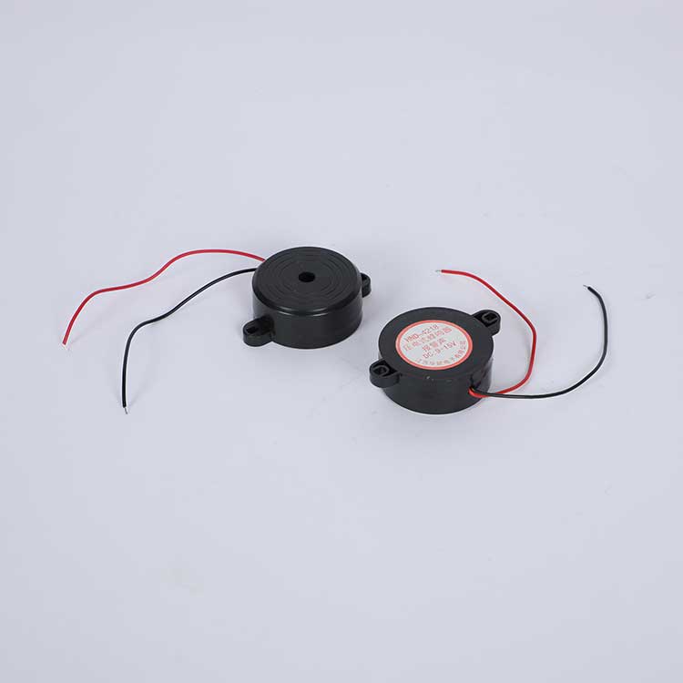
Engineers face unique challenges when choosing a piezo buzzer circuit. A piezoelectric buzzer acts as a capacitive load, requiring active charge management to achieve higher peak-to-peak voltage and target sound pressure levels. Selection depends on drive voltage from 3Vp-p to 24VDC, GPIO limits, and required volume between 75dB and 110dB. An active electronic piezo buzzer integrates an internal oscillator for plug-and-play operation. Conversely, a passive piezo buzzer requires an external drive circuit or PWM signal to produce sound. Understanding these options optimizes your overall buzzer circuit design.
TL;DR (Executive Summary)
The optimal piezo buzzer circuit depends on your SPL and power constraints. Direct GPIO drives suit low-cost indicators, while H-bridge and resonant LC circuits are mandatory for high-volume industrial alarms. For battery-powered IoT devices, dedicated driver ICs with integrated boost converters provide the most stable acoustic output. HUAWHA offers fully matched piezo components and SPICE models for all these topologies.
Key Takeaways
Direct microcontroller pins offer the simplest and cheapest design for basic sound alerts.
Single-transistor circuits boost sound volume by allowing higher operating voltages.
Resonant circuits use inductors to create maximum volume for loud industrial alarms.
H-Bridge circuits double the voltage to produce louder sound from small batteries.
Dedicated driver chips keep sound volume steady as battery power drains over time.
Direct Microcontroller Pin Driver for a Piezo Buzzer
Simple GPIO PWM Drive Topology
Connecting a passive piezo buzzer directly to a microcontroller unit (MCU) represents the simplest design approach. The MCU generates a square wave PWM signal from a single General-Purpose Input/Output (GPIO) pin. This signal toggles the pin high and low at the resonant frequency of the piezoelectric element. The alternating voltage creates mechanical motion within the internal ceramic disc. That physical vibration generates clear audio tones for simple notification alerts.
Note: Always verify your MCU output voltage matches the minimum rating of your piezo buzzer to ensure reliable operation.
Low Component Count and Cost Efficiency
Direct pin connection eliminates external switches, transistors, and complex ICs. Engineers value this minimal design for applications prioritizing board space and budget.
Minimal Bill of Materials (BOM) cost.
Low PCB surface area footprint.
Simple code implementation for tone control.
A single series resistor typically protects the GPIO pin against instantaneous capacitive charging spikes. This minimalist buzzer circuit suits simple status indicators effectively.
Current Limits and Reduced SPL Output
Microcontroller GPIO pins face strict electrical boundary limits when driving capacitive loads.
Electrical Parameter | Standard MCU Pin Limit | Design Requirement |
|---|---|---|
Sourcing DC Current | 25 mA Maximum | Requires series resistor (>200 Ω) |
Sinking DC Current | 25 mA Maximum | Prevents current overload |
Max Capacitive Spike Limit | 16 mA Peak | Protects internal GPIO clamps |
Because an MCU pin limits current, the voltage swing remains tied to the power supply rail ($V_{cc}$). This restricted voltage limits overall volume and frequency bandwidth.
Driver Parameter | Single GPIO Pin Drive | Bridged (H-Bridge) Drive | SPL Performance Impact |
|---|---|---|---|
Voltage ($V_{pp}$) | Limited to supply rail ($V_{cc}$) | Double supply rail ($2 \times V_{cc}$) | Lower $V_{pp}$ reduces radiated acoustic energy |
Excursion | Flexes in one direction | Flexes in two directions | Single pin drive cuts movement in half |
Acoustic Power | Wastes half voltage swing | Delivers $4\times$ power | Direct drive yields 6 dB lower SPL output |
This low-voltage drive mechanism cuts sound pressure levels significantly. Engineers needing high-volume alarms must explore boosted piezo buzzer driver circuit topologies.
Single-Transistor Buzzer Circuit Configurations
BJT and MOSFET Switching Techniques
A single-transistor piezo buzzer circuit offers a low-cost solution to boost signal levels beyond standard microcontroller limitations. Engineers can drive an NPN bipolar junction transistor (BJT) or an N-channel MOSFET as an electronic switch. The switch helps drive the system using low-voltage control signals from a microcontroller.
BJT Switching: Requires a base resistor to limit input current.
MOSFET Switching: Offers lower conduction losses and requires minimal gate current.
This simple buzzer arrangement allows the piezo buzzer to operate at supply voltages higher than the digital logic rail.
Parallel Resistors for Capacitive Discharge
A piezoelectric buzzer inherently acts like a capacitor during operation. When the transistor turns off, electrical charge remains trapped across the internal ceramic element. Placing a discharge resistor in parallel with the piezo buzzer creates a quick path to release this charge. Fast energy release enables the ceramic element to return rapidly to its resting state, producing clear sound alerts. Without this parallel resistor, the piezo buzzer retains voltage, reducing vibration amplitude and sound quality.
Power Dissipation vs. Volume Trade-Offs
Choosing the parallel resistor value involves strict trade-offs in power efficiency and audio performance.
Decreasing the value of the parallel resistor reduces electrical efficiency—leading to higher power dissipation—while simultaneously damping the transducer's mechanical resonance. Consequently, instead of increasing the piezo buzzer volume, lowering the resistance actually diminishes acoustic efficiency.
A small resistor drains extra current from the DC rail whenever the transistor switches on. Conversely, a large resistor slows down the capacitive discharge rate. Engineers must choose an optimal resistance value to balance piezo buzzer volume, power consumption, and thermal management for every passive piezoelectric buzzer application. This balance creates an effective buzzer circuit for high-volume piezo buzzer alarms.
Resonant and Self-Excitation Piezoelectric Buzzer Drivers
Parallel Inductor Resonant Boosting
Adding a parallel tuning inductor to a piezoelectric buzzer creates an inductive-capacitive (LC) resonant tank circuit. The inherent capacitance of the ceramic element interacts directly with the added inductance. At electrical resonance, this LC network acts as a passive voltage amplifier. The circuit transforms a standard low power supply into a high peak-to-peak voltage swing ($V_{pp}$).
Tip: Matching the inductor value to the precise capacitance of your transducer maximizes energy transfer and prevents unwanted electrical dampening.
Consequently, this inductive boosting technique increases sound pressure levels significantly. The setup enables a high-performance piezoelectric buzzer to generate loud output sound up to 110dB without adding extra amplifiers.
Three-Terminal Piezoelectric Transducer Feedback
A three-terminal self-exciting piezoelectric buzzer includes a primary driving electrode, a ground electrode, and a specialized feedback tap. This construction forms a closed-loop oscillator using a single switching transistor. The self-oscillating buzzer design simplifies hardware engineering while maintaining peak output. The continuous oscillation cycle operates through specific steps:
When voltage is applied, the transistor turns on and activates the piezo buzzer across the coil.
The center terminal (tap) of the three-terminal piezo grounds the transistor's base, immediately shutting the transistor off.
Deactivating the transistor turns off the piezo buzzer, which ungrounds and releases the transistor base.
The transistor returns to its initial conducting state, repeating the loop to sustain continuous oscillations.
This feedback loop eliminates external microcontrollers while driving the ceramic disc continuously at maximum mechanical flex.
Automatic Resonant Frequency Tracking
Temperature changes, enclosure design, and mounting stresses alter the natural resonant point of a piezo buzzer disc. Self-exciting drivers automatically track these natural mechanical shifts. The circuit adjusts its oscillation rate to match the physical resonance of the element. This continuous adjustment ensures maximum acoustic output from the piezo buzzer at all times.
System Requirement | Standard External Drive | Self-Excitation Tracking Drive |
|---|---|---|
Frequency Control | Fixed MCU PWM signal | Automatically matches physical resonance |
Volume Performance | Output drops when resonance shifts | Maintains maximum sound level continuously |
Circuit Design | Requires external clock source | Self-oscillating single transistor network |
Engineers select a piezo buzzer drive circuit to maximize sound output in demanding environments. Essential applications include automotive alerts, medical devices, uninterruptible power supply (UPS) systems, and industrial alarms. Industrial buzzer alerts demand constant output, making these resonant configurations ideal for security equipment.
To mitigate resonance shifting in harsh environments, HUAWHA Engineers recommend pairing their HNB-Series industrial piezo buzzers with self-excitation tracking drives. Operating across flexible drive voltage ranges from 3Vp-p to 24VDC, HUAWHA's proprietary ceramic doping process ensures reliable warning signals. Manufactured under certified ISO 9001 and ISO 13485 management systems, these RoHS-compliant components deliver clear sound performance in harsh industrial environments worldwide. Choosing a proper buzzer configuration enhances system reliability while meeting strict noise specifications.
Push-Pull and Full-Bridge Piezo Buzzer Circuit Options
Dual-Transistor Push-Pull Discharge
Single-transistor topologies often struggle with slow charge dissipation during high-frequency operation. Engineers often upgrade to a push-pull piezo buzzer circuit to improve switching speed and active charge control. A dual-transistor push-pull topology solves discharge delays by actively managing both charging and discharging cycles.
This circuit uses a complementary pair of transistors, such as an NPN and PNP pair or N-channel and P-channel MOSFETs. The top transistor connects the transducer to the positive power supply rail during the charge phase. The bottom transistor actively connects the positive terminal to ground during the discharge phase.
Push-Pull Topology Logic Flow:
Charge Phase: Top transistor (P-channel / PNP) connects transducer to +Vcc.
Discharge Phase: Bottom transistor (N-channel / NPN) actively pulls transducer to GND.
This active discharge network forces stored electrical charge out of the transducer quickly. This configuration actively discharges stored capacitive energy from the internal ceramic element of the piezo buzzer. Faster discharge times eliminate lingering mechanical vibrations, creating crisp acoustic output and clear sound. A dedicated push-pull switch maintains crisp tone quality for every warning buzzer.
Full-Bridge H-Bridge Voltage Doubling
An H-bridge driver topology maximizes acoustic volume without adding boost converters or bulky transformers. When system constraints limit the available drive voltage, this bridge configuration doubles the effective potential difference across the load.
Key Takeaway: A full-bridge driver places the piezoelectric buzzer between two half-bridge output stages operating 180 degrees out of phase. Two digital signals drive these half-bridge switches in opposing logic states.
When one side connects to the supply rail, the opposite side connects to ground, establishing a potential difference equal to the supply voltage in one direction. Reversing signal phases flips the polarity across the transducer element. This operation allows the overall differential voltage swing across the transducer to reach nearly twice the single supply voltage.
Parameter | Single-Ended Driver | Full-Bridge (H-Bridge) Driver |
|---|---|---|
Operating Voltage ($V_{cc}$) | 3.3V | 3.3V |
Voltage Polarity | Unipolar (0V to +3.3V) | Bipolar (+3.3V to -3.3V) |
Peak-to-Peak Voltage ($V_{pp}$) | 3.3V $V_{pp}$ | 6.6V $V_{pp}$ |
Relative Acoustic Output | Baseline (0 dB) | Up to +6 dB Increase |
For example, a standard 3.3V supply delivers a peak-to-peak differential voltage swing of 6.6V (+3.3V to -3.3V differentially) across the piezo buzzer. This bridged setup transforms an efficient low-voltage buzzer circuit into a high-output audio system.
Achieving Maximum Vpp and High SPL
Achieving maximum Sound Pressure Level (SPL) requires maximizing the differential peak-to-peak voltage ($V_{pp}$) across the ceramic disc. Doubling the voltage swing quadruples the available acoustic power. An H-bridge configuration quadruples radiated acoustic power compared to a single-ended piezo buzzer driver.
Higher differential voltage flexes the internal ceramic element further in both mechanical directions, producing louder sound. Consequently, this enhanced mechanical displacement increases sound pressure levels for any heavy-duty piezoelectric buzzer. Compact portable devices benefit greatly from this drive technique because it eliminates heavy magnetic components or high-voltage transformers. A compact piezo buzzer delivers loud alarm tones without draining excessive battery current.
Single-Ended Drive: Swings from [ 0V to +Vcc ] → Peak-to-Peak Voltage = Vcc
Differential H-Bridge: Swings from [ -Vcc to +Vcc ] → Peak-to-Peak Voltage = 2 × Vcc
Engineers select this high-performance configuration when designing critical safety alarms that demand maximum SPL. A high-output piezo buzzer alerts operators reliably in loud industrial environments. System designers can rely on a modern piezo buzzer to maintain stable acoustic performance across varying ambient temperatures. Engineers can easily drive these differential circuits using standard microcontrollers or dedicated differential driver integrated circuits. Integrating an H-bridge driver ensures that your piezo buzzer achieves full volume performance. This approach delivers maximum performance for every compact buzzer. Proper layout prevents noise from interfering with the main system buzzer. Modern security systems utilize this bridge topology for their primary alert buzzer.
Dedicated Driver ICs and Integrated Boost Converters
Integrated Charge Pump Architecture
Dedicated driver integrated circuits (ICs) provide advanced methods to drive an acoustic indicator. These specialized chips incorporate internal charge pumps or inductive boost converters. The internal converter elevates low battery power into a high drive voltage reaching up to 24V peak-to-peak. High differential potential maximizes mechanical flex within a piezoelectric buzzer element. Consequently, these smart driver chips generate high volume from low-voltage sources without requiring bulky external transformers. A modern piezo buzzer achieves superior audio performance through this compact active boost mechanism. Silicon chips effectively drive high-capacitance loads while keeping current draw minimal.
Constant SPL Across Battery Voltages
Battery-powered devices experience continuous voltage decay during normal operation. Unregulated circuits suffer from dropping audio volume as power degrades. Dedicated driver ICs regulate internal power rails to keep output levels perfectly steady. A compact piezo buzzer operates reliably across varying supply levels.
Note: A regulated boost circuit ensures consistent sound output across the entire discharge cycle of a lithium cell or coin battery.
This stable power delivery allows a piezo buzzer to output clear sound at all times. A miniature electronic piezo buzzer relies on controlled voltage rails to avoid tone distortion. Maintaining a constant volume prevents acoustic degradation in critical medical equipment and security alarm systems. The internal alarm buzzer maintains full operational volume until battery exhaustion.
Higher BOM Cost vs. Board Space Efficiency
Choosing dedicated ICs involves balancing financial investment against overall circuit size. Integrated driver solutions combine boost converters, switching transistors, and logic control into a single tiny package. An efficient warning buzzer demands precise charge management to avoid unwanted acoustic distortion.
Design Factor | Discrete Transistor Circuit | Integrated Driver IC |
|---|---|---|
PCB Area | Larger footprint | Compact silicon package |
BOM Cost | Extremely low budget | Higher unit cost |
Output Stability | Declines with battery voltage | Delivers uniform sound output |
This high integration reduces board space requirements for every portable piezo buzzer layout. Additionally, an ideal piezo buzzer driver maximizes energy efficiency in small handheld electronics. System engineers evaluate these cost trade-offs when optimizing a piezo buzzer setup for mass production. Selecting the proper driver chip ensures that your piezo buzzer meets strict acoustic standards efficiently. A dedicated alert buzzer protects critical system functions while saving physical space on the main board.
Drive Topology Selection Guide
Trade-offs in Complexity, Voltage, and Power
Selecting the optimal piezo buzzer circuit requires balancing system complexity, supply voltage, and power consumption. A simple buzzer circuit driven directly by microcontroller pins minimizes board components. However, direct pin connection limits overall sound performance. Single-transistor switches boost volume at higher supply voltages. Full-bridge topologies double peak-to-peak voltage, maximizing acoustic output without complex boost converters. Integrated driver ICs maintain regulated output across decaying battery voltages.
Selecting a Piezo Buzzer for Specific Applications
Engineers match driver choices to specific system requirements:
Design Tip: Always evaluate target sound pressure levels before selecting driver components.
Simple Notifications: A microcontroller pin can drive a passive piezo buzzer for status alerts in small devices.
Portable IoT Devices: Dedicated ICs drive an electronic piezo buzzer effectively while maintaining stable volume across battery cycles.
Loud Alarms: Resonant tank circuits allow a high-output piezo buzzer to generate loud warning tones up to 110dB.
Automotive Alerts: Differential H-bridge drivers enable a durable piezoelectric buzzer to deliver maximum output.
Application | Driver Topology | Primary Benefit | Recommended HUAWHA Series |
|---|---|---|---|
Compact Indicators | Direct GPIO Pin | Minimal board footprint | HNB-SMD Low-Profile |
Industrial Systems | Resonant LC Tank | High-decibel output | HNB-HighSPL (90-110dB) |
Portable Devices | Integrated Charge Pump | Stable volume | HNB-UltraLow Current |
System testing and regular troubleshooting reveal acoustic bottlenecks early in development. Choosing the right piezo buzzer guarantees optimal warning alerts for every buzzer installation. A proper piezo buzzer enhances user interaction across all operating conditions. Selecting a high-quality piezo buzzer ensures reliable long-term performance. Every safety alert buzzer relies on stable circuit design. A well-designed system buzzer provides clear feedback.
Selecting the right drive topology for your piezo buzzer circuit depends on system goals. Direct GPIO pins drive simple indicators. Single-transistor circuits balance budget and volume. Resonant networks power loud alarms, while H-bridge circuits deliver maximum sound from low battery voltages.
Key Takeaway: Quality acoustic components ensure reliable alert performance.
Match your drive circuit with a high-performance piezoelectric buzzer or an electronic piezo buzzer. Certified components built under ISO 9001, ISO 13485, and RoHS standards guarantee performance. Selecting a durable piezo buzzer ensures clear audio for automotive, industrial, and IoT applications. Choosing the proper alert buzzer enhances system reliability.
FAQ
What is the difference between an active and a passive piezo buzzer?
An active piezo buzzer contains an internal oscillator circuit. It produces sound directly from a DC power supply. Conversely, a passive piezo buzzer needs an external PWM signal to drive the ceramic disc.
How do I diagnose a buzzer not working in a circuit?
Start basic hardware troubleshooting by measuring operating voltage across terminals. Verify microcontroller PWM output signals using an oscilloscope. Inspect solder connections and ensure correct component values in your piezo buzzer driver circuit.
Why is my piezo buzzer producing weak acoustic output?
Low volume usually stems from limited peak-to-peak voltage swing. Microcontroller pins limit capacitive charging current. Upgrading to an H-bridge driver or boost converter maximizes differential voltage, creating louder sound.
What steps are included in troubleshooting buzzer performance?
Effective troubleshooting buzzer methods require checking drive frequency alignment. Ensure your input signal matches the mechanical resonant frequency. Unmatched frequencies reduce audio efficiency and alter expected acoustic responses.