

 doris@jshnbuzzer.com
Lead Buzzer Explained: A Comprehensive Guide
 Aug 24, 2026|
 View:411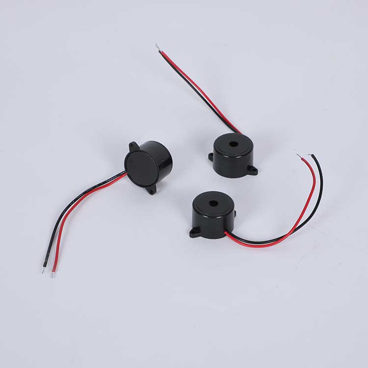
A lead buzzer is a specialized acoustic signaling component featuring pre-attached wire leads or extended pins, designed for versatile circuit integration and panel mounting. Unlike standard surface-mount devices, these buzzers offer unparalleled flexibility in PCB layout and enclosure design. They provide reliable audible alerts for medical devices, industrial alarms, and automotive electronics. The global buzzer market reached USD 763.07 million in 2025, with a growing demand for customized wire-harness acoustic solutions. This comprehensive guide explains the working principles, engineering advantages, and selection criteria for lead buzzers, helping hardware designers and procurement managers choose the optimal component for their projects.
Key Takeaways
Definition & Advantage: A lead buzzer features wire leads for easy connection, bypassing SMT heat restrictions and enabling flexible panel mounting.
Technology Split:Piezoelectric buzzers offer high efficiency and loud output, while electromagnetic buzzers excel in low-voltage, low-frequency applications.
Drive Modes: Active buzzers generate sound with DC power; passive buzzers require external MCU signals for customizable melodies.
B2B Customization: Lead buzzers support wire harness customization, including specific cable lengths and JST connectors.
Optimal Driving: Drive passive buzzers with a PWM signal matched to their resonant frequency to maximize Sound Pressure Level (SPL).
What Is a Lead Buzzer?
Definition and Mechanical Advantages
A lead buzzer is an acoustic transducer equipped with flexible wire leads or specialized extended pins. These leads serve as the electrical interface, connecting the internal oscillation circuit or piezo element to the main PCB or power source. This physical design distinguishes it from SMD buzzers (which require automated pick-and-place and reflow soldering) and standard DIP pin buzzers.
Why do engineers choose Lead Buzzers over SMD types? The primary advantage lies in thermal management and mechanical flexibility. SMD buzzers must endure 260°C reflow oven temperatures, which can sometimes degrade the acoustic cavity or internal magnets. Lead buzzers are typically hand-soldered or connected via headers post-assembly, preserving their acoustic integrity. Furthermore, wire leads allow the buzzer to be mounted directly onto the device's outer casing or control panel, ensuring sound projects outward without being muffled by a sealed PCB enclosure.
The basic function remains consistent across all models. The device produces sound when it receives proper electrical power. The tone characteristics depend on the internal construction. Some models generate a continuous tone, while others produce pulsed sounds. The operating voltage range typically spans from 3V to 24V, depending on the specific model.
High-Value Industry Applications
While consumer electronics use buzzers for basic alerts, lead buzzers are critical in high-reliability sectors where secure wiring and robust mounting are mandatory. The table below shows typical applications across advanced industries.
Industry Sector | Application of Lead Buzzers |
|---|---|
Medical Devices | Patient monitors, portable oxygen concentrators, and medical bed alarms (Requires ISO 13485 certified reliability). |
Industrial Controls | PLC status alerts, UPS fault alarms, and heavy machinery warning systems mounted on external panels. |
Automotive Electronics | Seatbelt reminders, parking sensor alerts, and dashboard notifications requiring vibration-resistant wire harnesses. |
Smart Home & Security | Smart locks, smoke detectors, and gas leak alarms where the buzzer must be routed to specific acoustic vents. |
These examples demonstrate how the buzzer provides essential feedback in critical environments. Each application requires specific sound characteristics and power requirements. Manufacturers select the appropriate buzzer model based on these needs.
Portable electronics also rely heavily on this component. Smartphones, tablets, and laptops use piezo buzzers for audio feedback on notifications, keypresses, and system alerts. Their compact size and efficiency allow integration into slim device designs while delivering clear sound. The small footprint of a lead buzzer makes it ideal for space-constrained products.
Industrial equipment uses lead buzzers for machine status indication. Control panels incorporate them to signal operation completion or fault conditions. Medical devices employ them for patient monitoring alarms. The versatility of this simple component makes it indispensable across many industries. Understanding these applications helps you identify where a lead buzzer fits your project requirements.
How a Lead Buzzer Works
The Transduction Mechanism
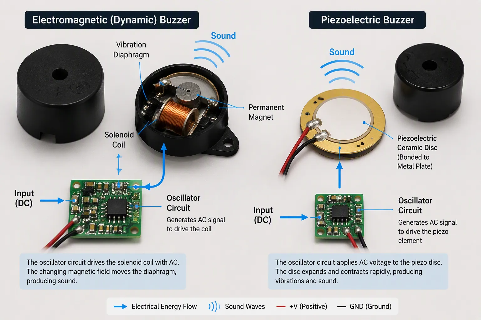
Every lead buzzer converts electrical energy into mechanical vibration to displace air and create sound waves. The underlying physics separates them into two main categories: electromagnetic and piezoelectric. Each type operates differently, yet both serve the same purpose of generating an alert tone.
An electromagnetic buzzer relies on electromagnetic induction. The device contains an oscillator, a solenoid coil, a permanent magnet, and a thin vibration diaphragm. When power flows through the coil, it generates a magnetic field. This field interacts with the permanent magnet, causing the diaphragm to flex. The oscillator drives this process with an audio signal current, producing periodic vibrations. These vibrations typically occur at a frequency between 2 and 4 kHz, which falls well within the human hearing range. The result is a clear, audible tone that can signal an alarm or notification.
A piezoelectric buzzer uses a different mechanism. The core element is a ceramic disc bonded to a metal plate. When an alternating voltage crosses the ceramic material, the disc expands and contracts rapidly. This deformation, known as the reverse piezoelectric effect, transfers mechanical motion to the metal plate. The plate vibrates like a miniature drumhead, displacing air and creating sound waves. The buzzer casing resonates at a specific frequency, amplifying the output. The sound pressure level scales directly with the applied voltage, so higher voltages produce louder tones.
The oscillator circuit plays a critical role in active buzzers. This internal circuit contains resistors, capacitors, and transistors that generate an electrical signal at a precise frequency. That frequency determines the pitch of the emitted sound. By adjusting the oscillator parameters, manufacturers can control the tone. Passive buzzers lack this internal circuit, so they require an external signal source, such as a microcontroller's PWM output, to produce sound.
Electromagnetic vs. Piezoelectric
Choosing between these two technologies requires understanding their differences. The table below summarizes key electrical parameters.
Parameter | Electromagnetic Buzzer | Piezoelectric Buzzer |
|---|---|---|
Operating voltage | 1.5V – 24V (Low Voltage) | 3V – 250V (Wide Range) |
Current consumption | 20mA – 100mA (Higher Draw) | < 30mA (Highly Efficient) |
Sound Characteristics | Lower pitch, softer tone | Higher pitch, sharp & piercing |
The electromagnetic buzzer operates at lower voltages but draws more current. It produces softer, lower-pitched tones suitable for basic alerts. Its construction makes it heavier and bulkier than piezo alternatives. Applications with limited circuit voltage often favor this type despite the higher current draw.
A piezoelectric buzzer operates at higher voltages with minimal current consumption. It produces higher sound pressure levels, making it louder than magnetic versions. Piezo buzzers support a wider frequency range, from sharp high-pitched tones to varied frequencies. Their response between input frequency and output audio power remains more linear, offering greater versatility. These characteristics make them ideal for portable devices where battery life matters.
Sound output differs noticeably between the two types. Piezo buzzers generate sharper, more piercing tones at higher resonant frequencies. Magnetic buzzers produce lower-pitched, softer sounds. For industrial alarms requiring high decibel output, a piezo buzzer often works best. For simple household alerts where circuit voltage stays low, an electromagnetic buzzer may suffice.
A practical example illustrates the piezo advantage. You can make a piezo buzzer sound by touching one lead while connecting the other to ground through a microcontroller pin. The microcontroller provides the alternating signal needed for vibration. This direct drive capability simplifies circuit design. An electromagnetic buzzer typically requires a transistor driver because of its higher current demand.
Understanding how the buzzer works guides your selection. The working principle determines sound output, power consumption, and driving requirements. Match these characteristics to your application's constraints for reliable performance.
Types of Lead Buzzers
Active vs. Passive Buzzers
The first major distinction between lead buzzers concerns their internal circuitry. An active buzzer contains a built-in oscillator. This internal circuit converts DC voltage into a periodic signal. The active buzzer can produce sound directly when connected to a battery. It operates within a voltage range of 1.5V to 24V and consumes ≤ 25mA current. An active buzzer includes an internal drive circuit. An external audio-frequency oscillator is not required.
A passive buzzer lacks this internal oscillator. It cannot produce sound directly from a battery. It requires an AC voltage signal to operate. Technical Note: For passive electromagnetic buzzers, the internal coil resistance is typically around 16 ohms, while passive piezo buzzers act as capacitive loads. Designers typically use a microcontroller PWM output to provide the necessary signal.
The table below compares the key features of both types.
Feature | Active Buzzer | Passive Buzzer |
|---|---|---|
Internal Oscillator | Built-in | None |
Required Input | DC voltage (3V-12V) | External square wave signal |
Sound Generation | Automatic, fixed tone | Requires external signal to produce sound |
Tone Flexibility | Fixed frequency (e.g., 2kHz) | Can produce a range of tones and frequencies |
For a simple alert system that needs a fixed tone, an active buzzer works well. HUAWHA offers models with operating voltages of 3V, 5V, 12V, and 24V. These buzzers are engineered to deliver high sound pressure levels for unmistakable alerts. For projects requiring variable sounds or melodies, a passive buzzer provides more flexibility.
Piezo vs. Electromagnetic Buzzers
The second major distinction focuses on the sound-generating mechanism. Piezo buzzers use a ceramic disc that vibrates when voltage is applied. An electromagnetic buzzer uses a coil and magnet to move a diaphragm. These two technologies differ in size, weight, and electrical requirements.
Piezo buzzers achieve a smaller form factor and lighter weight. Their thickness can be as low as 0.5 mm. Their diameter can be as small as 3 mm. An electromagnetic buzzer typically measures 2-10 mm in thickness. It ranges from 5-20 mm in diameter. This structural difference makes piezo buzzers ideal for compact battery-operated devices.
Electrical requirements also differ significantly. The table below shows typical operating parameters.
Parameter | Piezo Buzzers | Magnetic Buzzers |
|---|---|---|
Operating Voltage Range | 3V – 250V | 1.5V – 12V |
Current Consumption | < 10 mA | 20 mA – 60+ mA |
Piezo buzzers operate at higher voltages but draw very low current. This efficiency suits portable and battery-powered equipment. An electromagnetic buzzer operates at lower voltages. It draws more current. It produces softer tones suitable for basic household alerts.
HUAWHA manufactures both types of buzzer. Their product line includes piezo buzzers for high-efficiency applications. It also includes the electromagnetic buzzer for simple low-voltage circuits. Understanding these differences helps you choose the correct component for your design.
How to Choose a Buzzer

Selecting the right component for your project requires careful evaluation of several factors. The previous sections explained how different buzzers operate. Now you need practical guidance for making the final decision. This section covers the essential electrical parameters and physical considerations that determine which model fits your application.
Key Electrical Parameters
Every buzzer specification sheet lists several electrical values. Understanding these parameters helps you match the component to your circuit design. The following points represent the most critical factors.
Operating Voltage: The buzzer must match your circuit's voltage supply. A 5V model works with standard microcontroller projects. A 12V or 24V unit suits industrial control panels. Connecting a lower-voltage buzzer to a higher supply can damage the internal components.
Current Consumption: Battery-powered devices demand low current draw. A piezo buzzer typically consumes less than 30 mA. This efficiency extends battery life significantly. An electromagnetic buzzer draws more current, often between 30 mA and 100 mA. Choose accordingly for portable applications.
Resonant Frequency: This parameter affects sound quality and loudness. Thinner ceramic discs produce higher-pitched tones. Thicker discs generate lower frequencies. The resonant frequency determines how noticeable the sound appears in different environments.
Sound Pressure Level (SPL): This value indicates loudness measured in decibels. Larger buzzers can reach up to 110 dB. Smaller models produce lower output. The table below shows how SPL decreases with distance for a typical buzzer.
Distance
Sound Pressure Level (dB)
10 cm
90
20 cm
84
40 cm
78
100 cm
~70
Impedance: The buzzer's impedance must match the driving circuit. A mismatch causes reduced sound output or electrical issues. Check the datasheet for the specified impedance value.
Wire Harness Customization: Unlike off-the-shelf SMD components, lead buzzers offer significant B2B customization. You can specify custom wire lengths (e.g., 100mm, 150mm) and pre-crimped terminals like JST XH or PH connectors to streamline assembly line labor and prevent reverse-polarity wiring errors.
Compliance & Certifications: Ensure the wire insulation and internal components meet RoHS, REACH, and Halogen-free standards required for global export, alongside ISO 9001 and ISO 13485 manufacturing certifications.
Size and Environmental Factors
Physical size plays a significant role in buzzer selection. A compact piezo buzzer measures as small as 3 mm in diameter. This footprint fits neatly into wearable devices and handheld electronics. Larger electromagnetic buzzers provide higher sound output but require more board space. Consider your enclosure dimensions before making a choice.
Environmental conditions also influence performance. Temperature extremes affect buzzer operation. Most standard models operate reliably between -20°C and +70°C. Industrial environments with higher temperatures may require specialized versions. Humidity can corrode exposed leads and internal components. Select a sealed model for damp or outdoor applications.
The application context determines the ideal buzzer type. For a portable device, a piezo buzzer with low current draw works best. Its efficiency preserves battery power while delivering a clear audible alert. For an industrial alarm requiring high decibel output, an electromagnetic buzzer may serve better. These units produce louder tones at lower voltages, making them suitable for factory floor environments.
Consider the sound pressure level needed at the listener's position. The table above demonstrates that SPL drops as distance increases. A buzzer producing 90 dB at 10 cm delivers only about 70 dB at 1 meter. Calculate the required output based on your specific application distance. This calculation ensures the alarm remains audible where needed.
Finally, review the datasheet thoroughly before purchasing. HUAWHA provides complete specifications for every model. These documents list voltage ranges, current consumption, frequency response, and environmental ratings. Matching these values to your project requirements prevents costly redesigns. A careful selection process saves time and ensures reliable operation.
Practical Tips for Using Buzzers
Driving Circuits
Connecting an active buzzer requires minimal effort. The internal oscillator handles signal generation. You simply apply DC voltage across the leads. A direct connection from a power source works perfectly. For microcontroller projects, connect the positive lead to a digital output pin. Connect the negative lead to ground. A 100Ω resistor in series protects the pin from current spikes. The buzzer sounds when the pin goes HIGH and silences when LOW. Always use a flyback diode (like 1N4148) in parallel with the buzzer to protect your transistor from inductive voltage spikes when switching off.
Passive buzzers demand more attention. These components lack an internal oscillator. They require an external square wave signal. A microcontroller PWM output provides this signal. Match the PWM frequency to the buzzer's resonant frequency. Most passive units resonate between 2kHz and 4kHz. Driving even 100Hz off-resonance causes a 10dB drop in sound output. This difference significantly reduces audibility.
Higher current applications need a transistor switch. An NPN transistor amplifies the GPIO current. Place a base resistor between 1kΩ and 4.7kΩ. The transistor operates in saturation mode as a switch. When the GPIO outputs HIGH, base current flows. The transistor conducts, allowing larger current through the buzzer. A flyback diode suppresses voltage spikes when the transistor shuts off quickly.
For piezo elements, add a pull-down resistor parallel to the component. A piezo acts like a capacitor. This resistor ensures charge dissipation between cycles. The diaphragm returns to neutral position properly. A push-pull configuration doubles the peak-to-peak voltage. Two microcontroller pins or a bridge driver achieve this. The result is a significant increase in sound pressure level.
Common Mistakes to Avoid
Several wiring errors cause immediate damage or malfunction. Incorrect polarity ranks as the most frequent mistake. Reversing connections on an active buzzer can silence it. The error may damage protection diodes or stress the driving circuit. Always verify the positive and negative leads before applying power.
Overvoltage presents another serious risk. Exceeding the rated voltage overheats the internal element. Permanent damage occurs quickly. Check the datasheet for the maximum rating. Insufficient current causes weak sound or intermittent operation. A power supply that cannot deliver required current may also reset the microcontroller.
Poor grounding creates voltage drops and noise injection. High resistance in ground return paths leads to erratic behavior. Loose wiring and cold solder joints cause sporadic sound. These issues prove difficult to diagnose. Inspect all connections carefully during assembly.
Driving a passive buzzer outside its recommended frequency range reduces volume. The tone may become harsh or unstable. An electromagnetic buzzer with higher current demands requires proper transistor selection. Incorrect base resistor values cause weak switching or overheating. HUAWHA provides complete datasheets and technical support. These resources help you avoid common pitfalls and ensure reliable operation.
A lead buzzer serves as a versatile sound component for countless projects. Its working principle, whether piezoelectric or electromagnetic, determines sound output and power consumption. Matching electrical specifications to your application ensures reliable performance. Active models produce fixed tones with simple DC power. Passive versions require external signals for varied sounds.
Test your buzzer with a basic circuit using a microcontroller and LED. This setup confirms proper operation before full integration. Verify polarity and voltage ratings first. Now that you understand lead buzzers, explore the datasheets and start designing your next alert system.
FAQ
Can I drive a lead buzzer directly from a microcontroller pin?
Only if it is a low-current active buzzer (typically <30mA). Even then, it is highly recommended to use an NPN transistor (like 2N3904) as a switch and include a flyback diode to protect the MCU from back-EMF spikes. Passive buzzers always require a driver circuit.
How can I identify an active buzzer from a passive one?
Apply DC voltage across the leads. An active buzzer sounds immediately. A passive buzzer stays silent because it requires an external square wave signal to produce sound.
Why does my buzzer produce weak sound or no sound at all?
Check polarity first. Reverse voltage silences active buzzers. Verify the supply voltage matches the rated value. For passive buzzers, confirm the drive frequency matches the buzzer’s resonant frequency.
Can I adjust the volume of a lead buzzer?
Volume scales with applied voltage for piezo buzzers. Higher voltages produce louder tones. Do not exceed the maximum rated voltage to avoid damaging the internal element.
Why choose a lead buzzer with JST connectors over bare wires?
Pre-crimped JST connectors drastically reduce assembly time and labor costs on the production line. They also prevent reverse-polarity wiring mistakes, which can permanently destroy the internal IC of an active buzzer.