

 doris@jshnbuzzer.com
Active vs. Passive SMD Buzzers: A Hardware Engineer's Guide
 Aug 31, 2026|
 View:385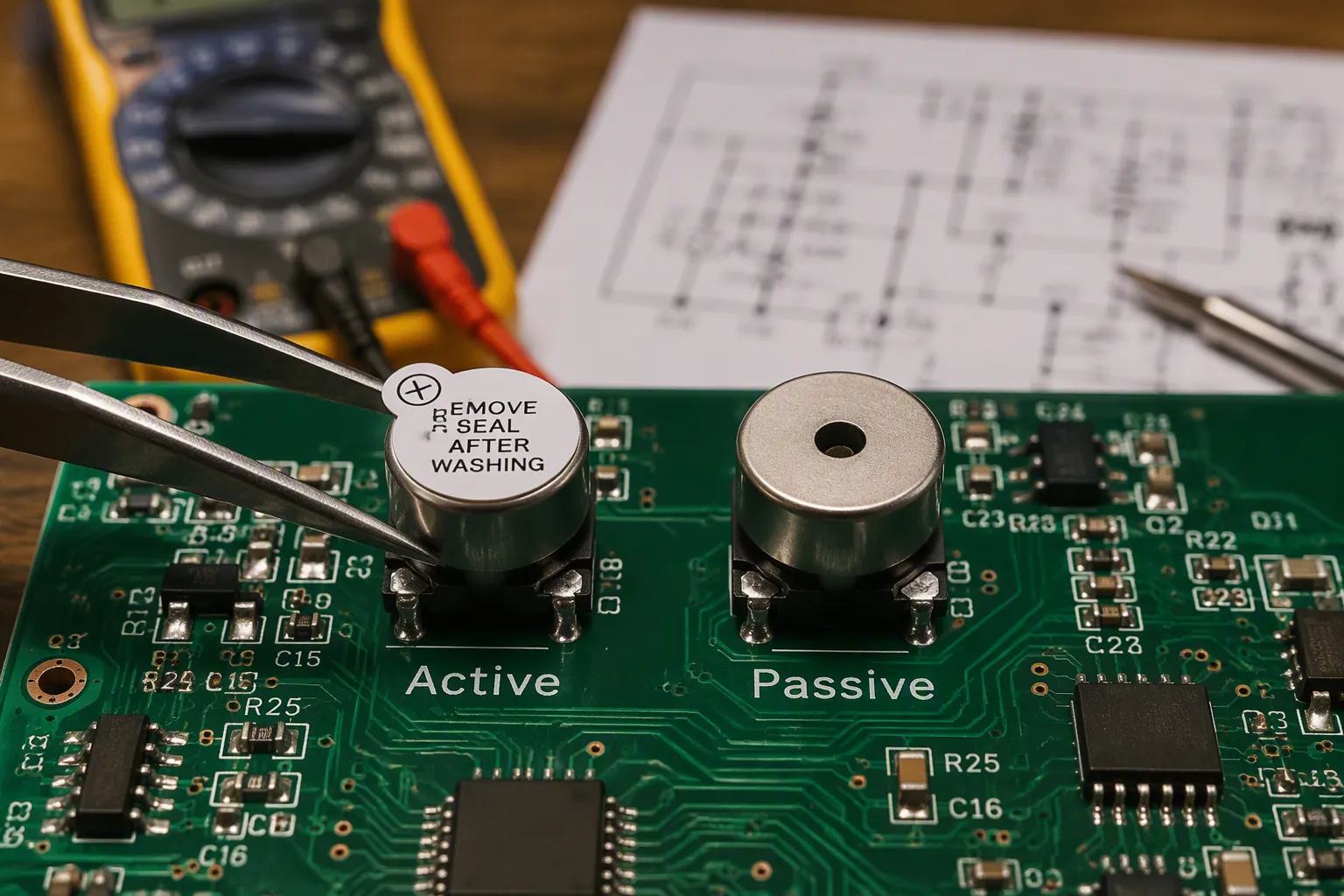
The fundamental difference between active and passive buzzers determines their drive requirements. An active buzzer contains a built-in oscillator and produces a fixed tone when powered with DC. A passive buzzer lacks this internal oscillator and requires an external AC signal (PWM) from a microcontroller.
The core engineering trade-off involves simplicity versus flexibility. For simple alerts, an active surface-mount buzzer minimizes drive circuit complexity. For melodies or adjustable sound, choose a passive buzzer. Understanding this distinction is the first step in hardware component selection for your PCBA.
Key Takeaways
Active buzzers have a built-in oscillator, so they produce a fixed tone with simple DC power.
Passive buzzers need an external PWM signal, which allows variable tones and melodies.
Choose active buzzers for simple alerts and low-power designs.
Choose passive SMD transducers for pitch control and complex sounds.
Piezo buzzers draw low current, while magnetic buzzers handle lower voltages.
Active vs. Passive Buzzers
Active Buzzers: Fixed Tone, Simple Drive
Active buzzers contain a built-in oscillator circuit. This internal component generates a fixed-frequency tone when the buzzer receives a direct current (DC) power source. The typical DC voltage range required to activate the oscillator is between 3V and 12V. Once powered, the buzzer automatically produces a sound at a predetermined frequency, such as 2kHz or 4kHz. The design engineer does not need to supply any external signal. This simplicity makes active buzzers an excellent choice for basic alerting functions.
The drive circuit for an active buzzer requires very few components. A simple transistor switch and a DC power source are sufficient. The microcontroller only needs to turn the transistor on or off. This approach minimizes PCB complexity and reduces the bill of materials. Active buzzers are available in both piezo and magnetic variants. Piezo active buzzers draw very low current, making them suitable for battery-powered devices. Magnetic active buzzers operate at lower voltages and produce higher sound pressure levels. Engineers select the appropriate type based on voltage and current constraints. Active buzzers serve well in applications where a single, consistent alert is sufficient.
Passive Buzzers: Variable Tone, More Control
Passive buzzers lack an internal oscillator. They require an external alternating current (AC) signal to produce tone. A microcontroller typically generates this signal using pulse-width modulation (PWM) or a square wave. The PWM frequency range for driving passive buzzers extends from approximately 2 kHz to 10 kHz. Within this range, specific frequencies map to musical notes. For example, a frequency of 2441 Hz corresponds to the note C, and 2741 Hz corresponds to D. Higher frequencies up to 4882 Hz produce the next octave. This capability allows passive buzzers to play melodies and multi-tone alerts.
The flexibility of passive buzzers enables volume control and pitch variation. The engineer can change the frequency and duty cycle of the PWM signal to adjust the tone. This feature is valuable for products that require distinct alerting functions. A passive buzzer requires more GPIO resources and software overhead. However, each buzzer type offers distinct advantages. Piezo passive buzzers offer a linear relationship between input drive signal strength and output audio power, which supports tunable tones. Piezo elements are common in these designs. The choice between piezo and magnetic passive buzzers depends on the design requirements. Magnetic passive buzzers exist but tend to maintain a more fixed tone characteristic. Magnetic variants handle higher current requirements. Passive buzzers are ideal for complex audible feedback.
The 4 Combinations: Active/Passive vs. Piezo/Magnetic
While "Active vs. Passive" defines the drive circuit, "Piezo vs. Magnetic" defines the acoustic technology. Hardware engineers typically choose from four main SMD combinations:
Active Piezo SMD: Best for high-SPL, low-power battery alarms. (e.g., HUAWHA 5V 85dB Active Piezo Series).
Passive Piezo SMD (Transducer): Ideal for complex melodies in wearables. Requires AC drive but offers ultra-thin profiles.
Active Magnetic SMD: Great for 1.5V-5V low-voltage applications needing a warmer, smoother tone.
Passive Magnetic SMD: Used when low-frequency, warm audio feedback is needed, but requires careful current management.
Buzzer Specifications Comparison
Voltage, Current, and SPL for Buzzers
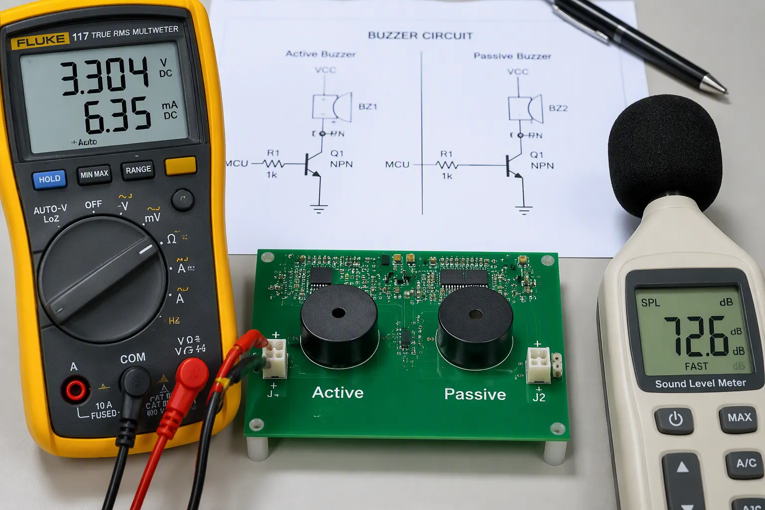
Selecting the right component requires a clear view of electrical and acoustic specifications. The three most critical parameters are operating voltage, current consumption, and sound pressure level (SPL). These values determine whether a buzzer fits the power budget and audible output requirements of a design.
Drive Type | Voltage Range | Notes |
|---|---|---|
Self-drive (indicator) | 3–28 Vdc | Includes SMD indicators (e.g., 12VDC, 3V, 5V) |
Non-self-drive (transducer) | 1–60 Vp-p | Includes SMD transducers (e.g., 3.6Vo-p, 5Vp-p) |
Common SMD products | 3V, 5V, 12V | HUAWHA SMD Active & Passive Series |
Typical SMD buzzers operate at voltages between 3V and 5V. This range covers most microcontroller-based designs. Active buzzers have a voltage range of 3V to 12V and low current consumption. A small active buzzer operates from 3V to 12V with a low current draw. These figures help engineers estimate buzzer power consumption early in the design phase.
Piezo electric buzzer performance is directly linked to voltage. A higher driving voltage generally results in a louder sound.
The relationship between SPL and voltage differs fundamentally between the two buzzer types. For piezo buzzers, SPL increases with higher driving voltage, exhibiting a reasonably linear relationship between input drive signal strength and output audio power. In contrast, magnetic buzzers show a rapid decline in audio output when the input drive signal decreases. Additionally, using a full bridge driver doubles the voltage applied to a piezo transducer, resulting in an SPL increase of approximately 6 dB.
Piezo buzzers: Produce very high SPL (85dB to 120dB), with sharp peaks of extreme amplitude on a frequency response graph.
Magnetic buzzers: Produce lower, more moderate SPL (70dB to 95dB), with a smoother frequency response curve.
Driving either type with an input signal matching its resonant frequency creates the greatest SPL with the least input power.
Frequency Range and Tolerances
Frequency response defines the tonal character of each buzzer type. Piezo buzzers offer a more linear relationship between input drive signal strength and output audio power, enabling tunable tones across a wide band. Magnetic buzzers maintain a fixed tone with a smoother response curve. This distinction affects buzzer sound quality and suitability for specific alert patterns.
Frequency tolerance is an important consideration for consistent tone production across production runs.
This tolerance matters when multiple buzzers must produce consistent tones across a production run. A typical variation can affect tonal consistency. For melody generation, the variation is usually acceptable. For precision alarms, tighter tolerances may be necessary. Engineers should request tighter specifications when exact pitch control is required.
The frequency range also influences drive circuit design. Piezo buzzers respond well to PWM signals across a broad spectrum. Magnetic buzzers operate best within a narrower band. Understanding these limits helps engineers match the buzzer to the microcontroller's capabilities. The choice between piezo and magnetic technology ultimately depends on the required sound profile and the available drive resources.
PCB Design for Surface-Mount Buzzers
Drive Circuit for Active vs. Passive Buzzers
The drive circuit for an active surface-mount buzzer remains remarkably simple. A standard low-side drive using an NPN transistor or N-channel MOSFET is most common. The microcontroller sends a high-level logic signal to the base/gate, turning the transistor on and grounding the buzzer. This requires minimal components: a transistor, a base/gate resistor, and a decoupling capacitor. The simplicity reduces the component count on the PCB and frees up valuable GPIO pins for other functions.
Passive buzzers demand a more careful drive arrangement. Crucially, a microcontroller GPIO pin must NEVER drive a passive buzzer directly, as the current draw can exceed the MCU's absolute maximum ratings and destroy the chip. Instead, the GPIO must drive a transistor or MOSFET, which then switches the higher current required by the buzzer. Furthermore, if driving a magnetic passive buzzer (which is an inductive load), a flyback diode (freewheeling diode) must be placed in parallel with the buzzer to protect the transistor from inductive voltage spikes when turned off. The added complexity pays off with full control over pitch and volume.
Footprint and Thermal Management for SMD Buzzers
The compact SMD package of a surface-mount buzzer requires careful footprint design. The recommended land pattern appears in the component datasheet. Engineers should follow these dimensions precisely. The pad size and spacing affect solder joint reliability. A proper footprint prevents tombstoning during reflow. The buzzer body sits above the pads, leaving a small gap. This gap allows sound to escape from the sound port.
Thermal management during reflow soldering demands attention. Lead-free reflow profiles reach high peak temperatures that can damage the internal piezoelectric element. Ceramic depolarization and micro-cracks may occur at high temperatures. The recommended safe limit follows the manufacturer's profile with a specified peak temperature. Always verify the maximum peak temperature rating in the specific component datasheet. The reflow profile should include a gradual ramp-up and a controlled cooling phase. This approach protects the piezo element while ensuring a solid solder joint. Magnetic buzzers tolerate similar thermal conditions, but their coil windings may shift with rapid temperature changes. A slower cooling rate reduces mechanical stress on the internal structure. Proper thermal management extends the operational life of the buzzer and maintains consistent sound output.
How to Choose Your Buzzer
Buzzer Selection Criteria
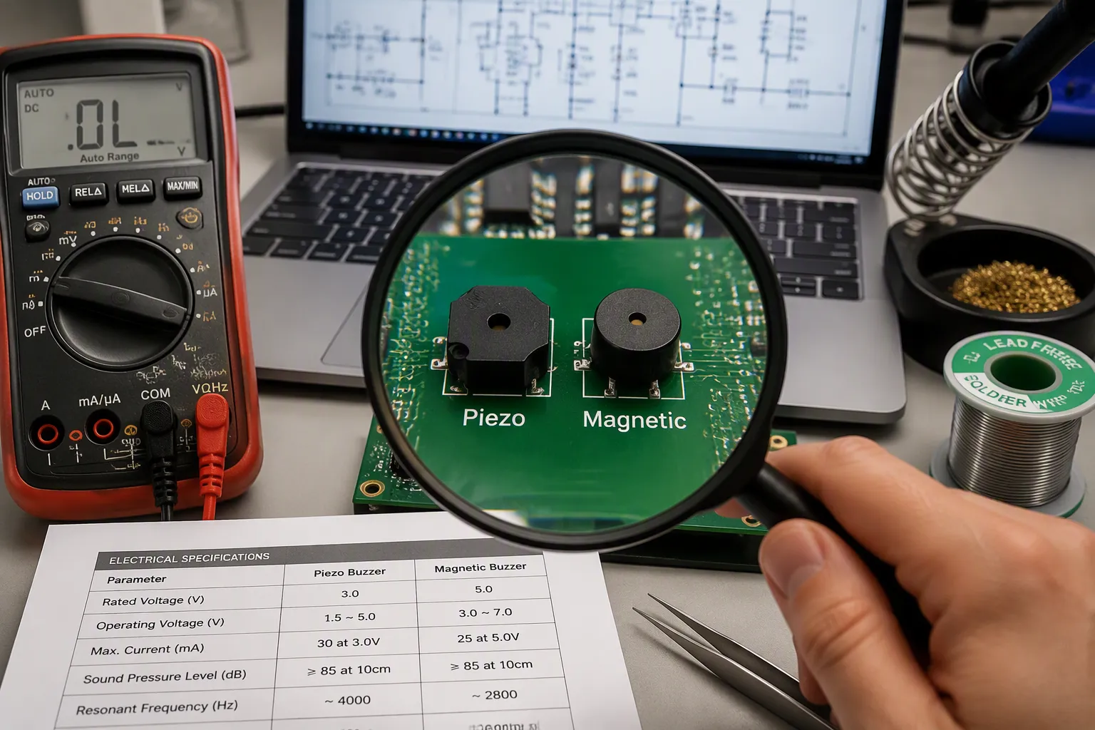
Selecting a buzzer for a new design requires a systematic evaluation of several interdependent factors. The operating environment, power budget, and desired audible output all influence the final component choice. Engineers must weigh tone flexibility, buzzer power consumption, drive complexity, physical size, and long-term reliability. This selection process determines the suitability of the component for the intended application.
Voltage compatibility stands as the first checkpoint. The rated voltage of the buzzer must match the available power supply. Common values include 3V, 5V, and 12V. A mismatch forces additional regulation circuitry, increasing cost and board space. Current consumption follows closely. For battery-powered devices, buzzer power consumption becomes a primary selection criterion. Piezoelectric buzzers draw very low current, making them ideal for IoT sensors and portable medical monitors. Magnetic buzzers draw 20 mA to over 60 mA, limiting their suitability for energy-constrained designs. The choice between piezo and magnetic technology directly affects the power budget.
Sound pressure level requirements depend on the application environment. In a quiet office, a moderate SPL may suffice. On a factory floor with hearing protection, a higher SPL is necessary. The SPL must be evaluated at the actual distance from the listener. A common mistake is selecting by nominal decibel value alone without considering ambient noise, barriers, and room acoustics. Audibility must be validated in the operating environment, not in a quiet lab. The buzzer sound quality must match the intended alert function. A shrill tone suits emergency alarms, while a smooth tone works better for user interface feedback. The sound from a magnetic buzzer offers a warmer character.
Environmental conditions also affect reliability. Standard consumer piezo buzzers operate within a moderate temperature range. Ruggedized industrial versions extend to higher and lower temperatures. For medical devices, compliance with relevant standards is critical. Specialized medical buzzers generate tones that correspond to specific alarm standards. Using such components simplifies design and ensures regulatory compliance. The durability of magnetic buzzers suits industrial environments.
Drive complexity directly impacts time-to-market. Active buzzers require only a simple transistor switch and a DC power source. This plug-and-play approach reduces prototype design time significantly. Passive buzzers demand an external PWM signal, increasing software overhead and circuit complexity. However, the trade-off yields greater frequency flexibility. Passive buzzers can produce a wide range of tones, while active buzzers produce a fixed frequency. For alerts requiring melody or pitch variation, the passive route is necessary. The suitability of each type depends on the available GPIO resources.
Mounting constraints also guide the selection. A surface-mount buzzer conserves pcb board space for compact designs. The footprint must match the recommended land pattern to ensure reliable solder joints. Thermal management during reflow requires adherence to the manufacturer's peak temperature rating to avoid damaging the internal piezoelectric element. The choice between top port and side port configurations affects the pcb layout and enclosure design.
Comparison Table: Active vs. Passive
The following table summarizes the key differences between active and passive buzzers to help engineers evaluate their options.
Feature | Active Buzzer | Passive Buzzer | HUAWHA Recommended SMD Solution |
|---|---|---|---|
Drive Circuitry | Built-in oscillator | External PWM signal required | N/A |
Design Effort | Minimal – plug-and-play | High – must design external driver | N/A |
Frequency Flexibility | Fixed frequency only | Variable frequency | N/A |
SPL Range | Varies by type | Varies by type | N/A |
Current Consumption | Low (piezo: very low) | Higher (magnetic: 20–60 mA) | N/A |
Impact on Prototype Time | Reduces design time | Adds complexity and time | N/A |
Typical Applications | Simple alerts, low-power devices | Melodies, multi-tone alarms | Active: MLT-9650Y Series (5V/12V Active SMD) |
Buzzer Sound Quality | Fixed tone, shrill | Tunable, smoother options | N/A |
The choice between active and passive ultimately depends on the specific requirements of the project. For simple alerts with minimal circuit complexity, active buzzers provide a straightforward solution. For applications requiring pitch variation, melody, or volume control, passive buzzers deliver the necessary flexibility. Evaluating buzzer application suitability requires matching the component's capabilities to the design constraints. Factors such as buzzer power consumption, tone flexibility, and drive complexity all contribute to the final decision. Engineers must choose the correct buzzer type based on their project's unique needs. The table helps engineers quickly assess the suitability of each option for their specific applications. A surface-mount buzzer from a reliable supplier simplifies procurement and ensures consistent quality.
The choice between active and passive buzzers ultimately depends on your project's specific constraints. Active buzzers excel in fixed-tone alert applications where circuit simplicity matters most. Passive buzzers provide the flexibility needed for melodies and variable pitch control. Consider your power budget, available GPIOs, and required sound output. Piezo buzzers offer low current draw, while magnetic variants deliver robust performance at lower voltages. Both buzzer types serve distinct applications across industries. Evaluate your design requirements carefully. A simple transistor switch suffices for active buzzers. Passive buzzers demand PWM-capable pins and software overhead. Consult the comparison table above to match your needs. For reliable component selection, contact HUAWHA for expert guidance on your specific buzzer requirements.
FAQ
What is the main difference between active and passive buzzers?
Active buzzers contain a built-in oscillator. They produce a fixed tone when powered with DC voltage. Passive buzzers lack this internal component. They require an external PWM signal from a microcontroller to generate sound. This distinction determines drive circuit complexity and tone flexibility.
How do I choose between piezo and magnetic buzzers?
Piezo buzzers operate at higher voltages from 3V to 30V. They draw very low current. Magnetic buzzers work at lower voltages from 1.5V to 12V. They consume more current, typically above 20mA. Consider your power budget and required sound pressure level when selecting between these buzzer types.
What drive circuit does each buzzer type need?
Active buzzers require only a simple transistor switch. A single NPN transistor or MOSFET and a few resistors suffice for low-side driving. Passive buzzers need a PWM-capable GPIO pin driving a transistor. This adds software overhead but enables variable tone control for melodies and multi-tone alarms.
Can passive buzzers produce different tones?
Yes. Passive buzzers accept PWM frequencies from approximately 2kHz to 10kHz. Each frequency maps to a specific musical note. Engineers can change the frequency and duty cycle to adjust pitch and volume. This flexibility makes passive buzzers ideal for applications requiring distinct alert patterns or melodic sequences.
What should I consider for SMD buzzer PCB design?
Follow the manufacturer's recommended land pattern for the footprint. Verify the peak reflow temperature rating. Higher temperatures can damage the internal piezoelectric element. Place a decoupling capacitor near the buzzer to stabilize power supply noise. These steps ensure reliable solder joints and consistent sound output.